
Efficient method of data transfer between register files and memories

a register file and memory technology, applied in the field of computer memory systems, can solve the problems of slowing down the effective speed of the processor core, /b> of performing data swap, and complex and time-consuming processes, and achieve the effect of efficient methods

Active Publication Date: 2006-11-14
ORACLE INT CORP
View PDF9 Cites 31 Cited by
  • Summary
  • Abstract
  • Description
  • Claims
  • Application Information

AI Technical Summary

Benefits of technology

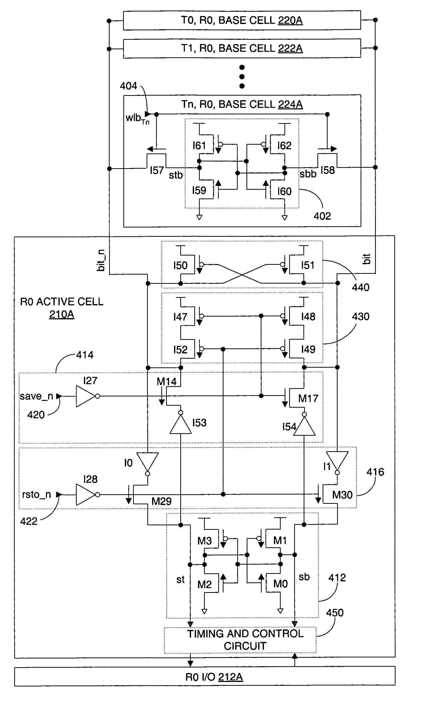
"The present invention provides a more compact memory system and a more efficient method of transferring data between cells in the memory system. This is achieved by including an active storage circuit and at least one base storage circuit connected through at least one pass gate, at least one driver, and a bit line. The base storage circuit can include multiple base storage circuits and each one of the base storage circuits corresponds to a processing thread in a multi-thread processor. The memory system can also include a pre-charge circuit, a keeper circuit, and a timing and control circuit. The method of swapping data between two storage circuits includes activating a first pass gate and a second pass gate between the two circuits and driving the data stored in the first circuit to the first bit line and the data on the first bit line to the second circuit. The method can also include applying a keeper circuit to the first bit line and the second bit line. The technical effects of the invention include a more efficient use of space and faster data transfer between cells in a memory system."

Problems solved by technology

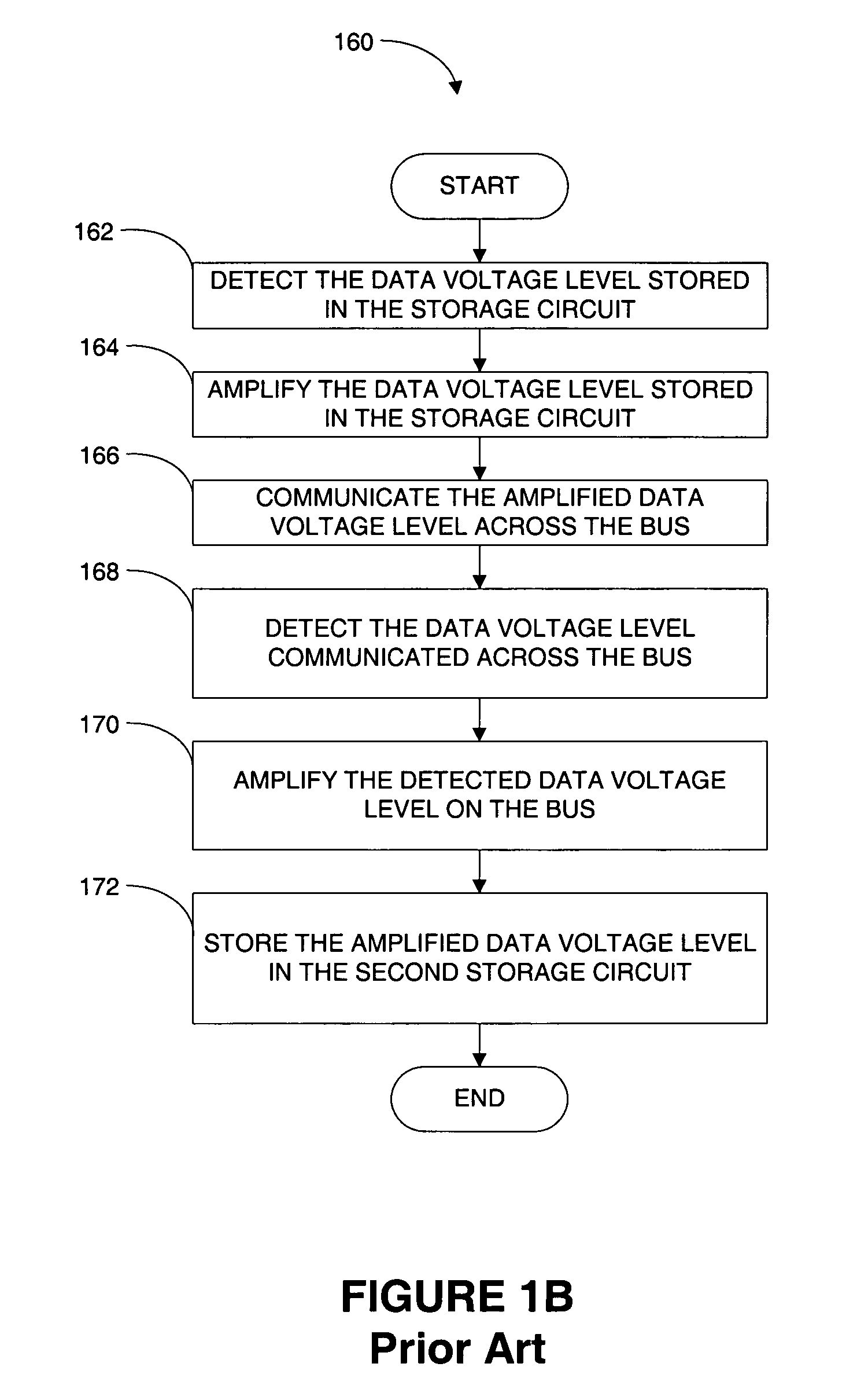
The method operations 160 of performing the data swap is a very complex and time consuming process as the data voltage level must be amplified and detected multiple times and communicated a relatively long distance across the bus 130.
This time consuming process slows down the effective speed of the processor core 150.

Method used


Image

  • Efficient method of data transfer between register files and memories
  • Efficient method of data transfer between register files and memories
  • Efficient method of data transfer between register files and memories

Examples


Embodiment Construction

[0035]Several exemplary embodiments for a more compact memory system and a more efficient method of transferring data between cells in the memory system will now be described. It will be apparent to those skilled in the art that the present invention may be practiced without some or all of the specific details set forth herein.

[0036]As described above it is often desirable to transfer data between two memory locations. By way of example, a processor may be processing a first set of data to a first interim result using a portion of active memory (e.g., an active register). The processor may be unable to fully process the first set of data to achieve a final result because the processor needs a second set of data that is not yet available. As a result, the first interim results and possibly even the first set of data may be transferred from the active register to a second storage location. The processor can then transfer other data to the active register and process the other data to ...


PUM


Abstract

A memory system includes an active storage circuit and at least one base storage circuit. The at least one base storage circuit is coupled to the active storage circuit though at least one pass gate, at least one driver and a bit line. The at least one pass gate and the at least one driver have a device size substantially similar to a device size of each one of the devices in the active storage circuit and the at least one base storage circuit. A method of swapping data between two storage circuits is also described.

Description

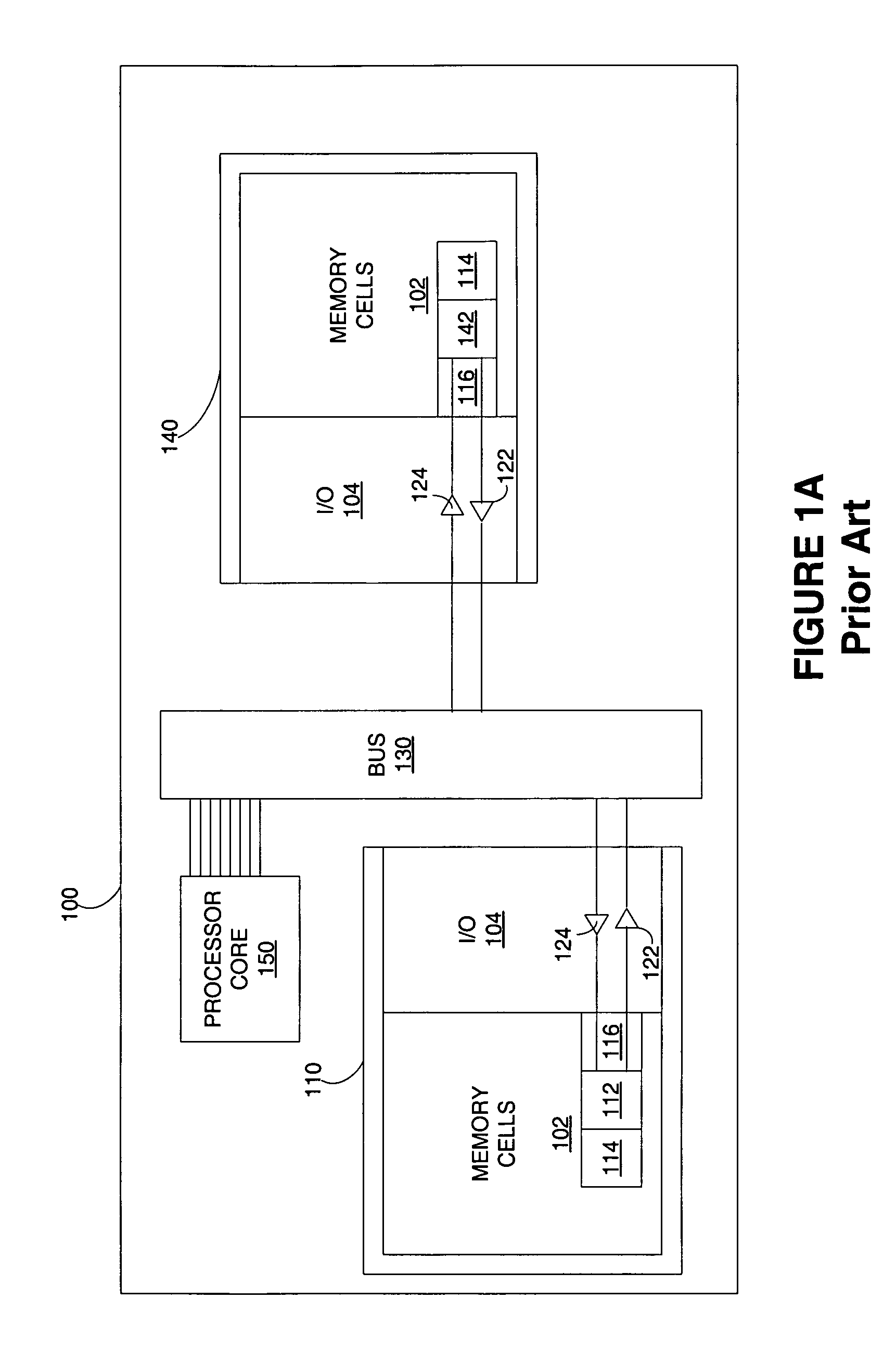
BACKGROUND OF THE INVENTION[0001]1. Field of the Invention[0002]The present invention relates generally to computer memory systems, and more particularly, to methods and systems for moving data between two memory locations.[0003]2. Description of the Related Art[0004]Computer memory systems are very common and are used in many different configurations. A typical block of memory includes a block of memory cells and input and output circuitry that allows the block of memory cells to communicate with a device or system that is external to the block of memory.[0005]FIG. 1A shows a typical microprocessor 100. The microprocessor 100 includes a first block of memory 110 includes a block of memory cells 102 and a block of input and output (I / O) circuitry 104. Each one of the memory cells 102 includes a storage circuit 112 (e.g., cross-coupled inverters), one or more keeper circuits 114, and pre-charge circuits 116. The storage circuit 112 stores a selected voltage level that corresponds to ...

Claims


Application Information

Patent Timeline
Patent Type & Authority Patents(United States)
IPC IPC(8): G11C7/10G11C7/24G11C11/419
CPCG11C7/10G11C7/24G11C11/419G11C11/413
Inventor KANT, SHREETAM, KENWAYKONGETIRA, POONACHA P.LIN, YUAN-JUNG DLIU, ZHEN W.AINGARAN, KATHIRGAMAR
Owner ORACLE INT CORP
Learn More