Loudspeaker device

a loudspeaker and speaker technology, applied in the direction of transducer casings/cabinets/supports, frequency response correction, electrical transducers, etc., can solve the problems of ineffective sound absorption materials, difficult to flatten the sound output characteristic, and inability to control a certain desired frequency component, etc., to achieve the effect of suppressing peaks and dips in the frequency characteristics of sound pressure and stable characteristics

Inactive Publication Date: 2006-11-14
PANASONIC CORP
View PDF5 Cites 5 Cited by
  • Summary
  • Abstract
  • Description
  • Claims
  • Application Information

AI Technical Summary

Benefits of technology

[0013]A speaker device of the present invention comprises a power amplifier which receives input signal via subtracter, a speaker unit for reproducing output signal of the power amplifier, an acoustic pipe coupled to the speaker unit in the front for guiding sound waves generated by the speaker unit, a microphone for detecting acoustic outputs radiated from the speaker unit, and a microphone amplifier for amplifying acoustic output signals detected by the microphone. In a speaker device having the above-described configuration, output signals of the microphone amplifier are delivered to the subtracter, and, at the same time, output signals of the above microphone amplifier are delivered via a high-pass filter also to the substracter to form a negative feedback circuit in order to suppress peaks and dips in the sound pressure frequency characteristics. Thus, the speaker device is provided with stable characteristics.

Problems solved by technology

However, the sound absorbing material is not effective enough to suppress the standing waves completely.
So, it has been difficult to flatten the sound output characteristic.
Furthermore, since the feedback is performed for an entire frequency range from a low frequency component to a high frequency component, it is impossible to control a certain desired frequency component.
This makes it difficult to apply too many feedbacks taking an oscillation margin into consideration, and to effectively control a low frequency region and a pipe resonance.

Method used


Image

  • Loudspeaker device
  • Loudspeaker device
  • Loudspeaker device

Examples


first embodiment

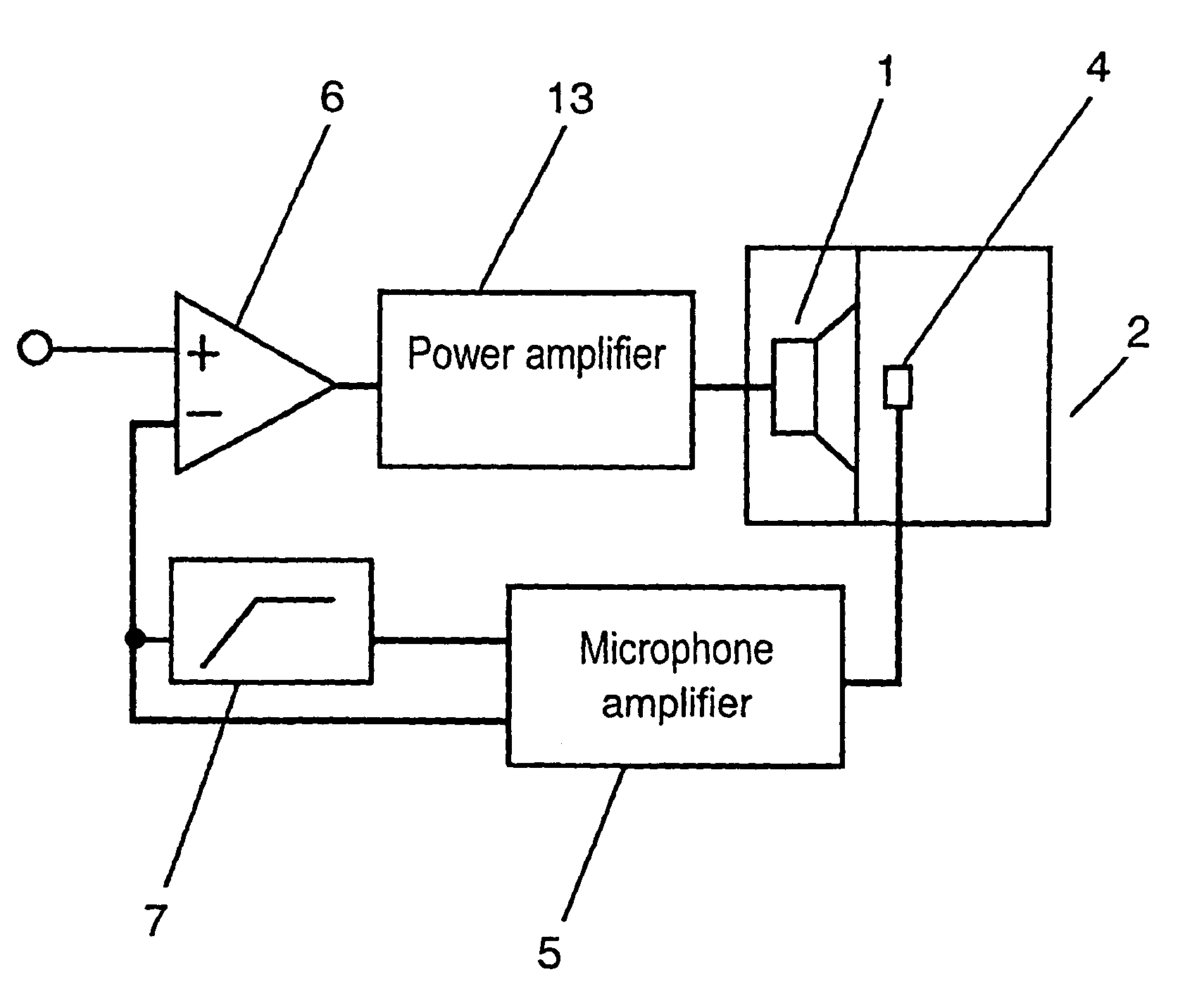
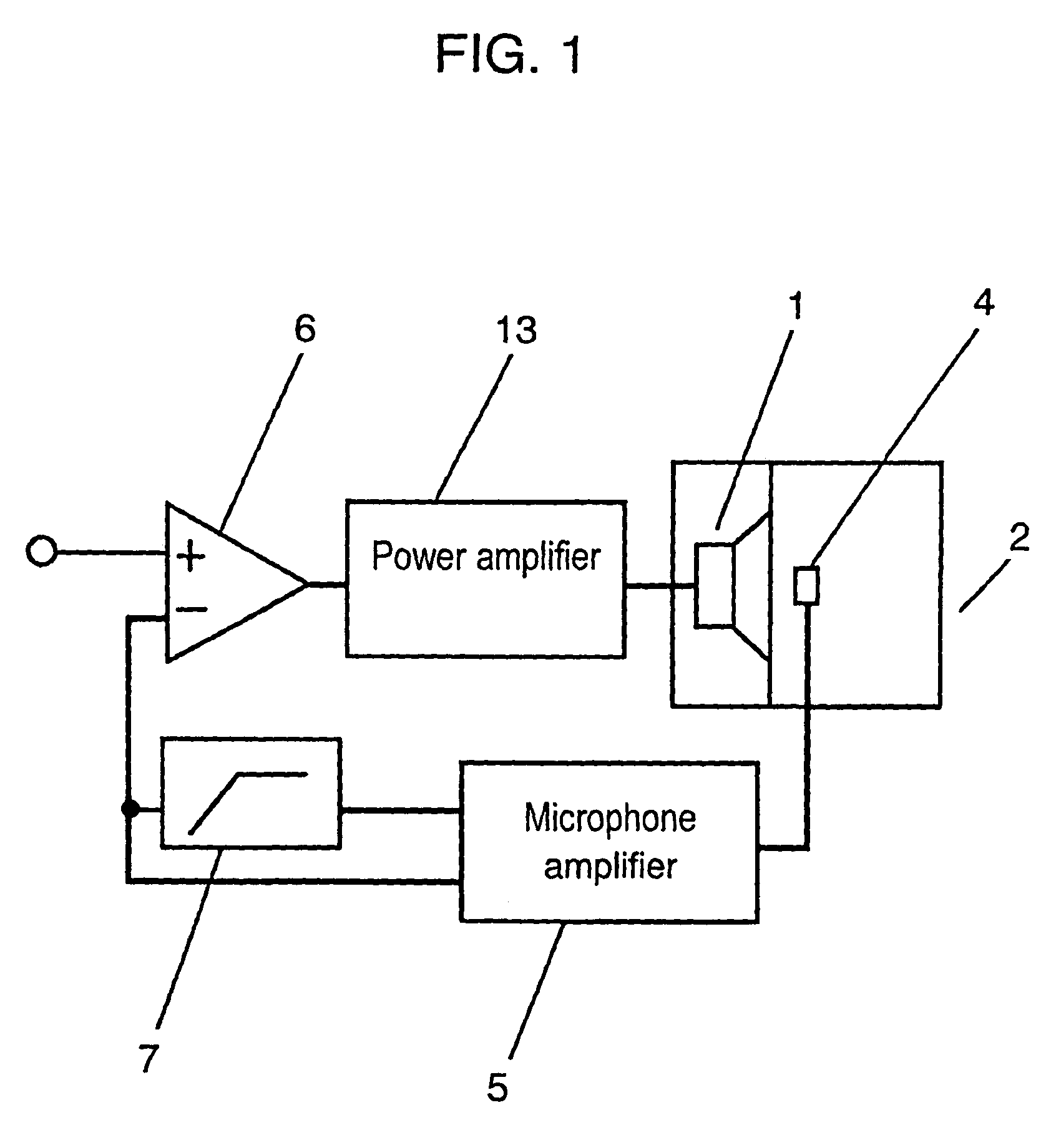
[0027]FIG. 1 shows a block diagram of an acoustic circuit in accordance with a first exemplary embodiment of the present invention. FIG. 2 is a sound output characteristic chart; where, curve “a” shows the sound pressure characteristic, while curve “b” shows the phase characteristic. Initially, the overall structure of the speaker device is described referring to FIG. 1.

[0028]Referring to FIG. 1, in front of a speaker unit 1 an acoustic pipe 2 is coupled to the speaker unit 1, and a microphone 4 is mounted within the acoustic pipe 2. Sound waves radiated from the speaker unit 1 are detected by the microphone 4 within the acoustic pipe 2. The detected signals are delivered to a subtracter 6 via a high-pass filter 7, and at the same time, the signals detected by the microphone 4 are input directly to the subtracter 6 to be mixed with input signals coming from outside in order to correct the input signals. The corrected signals are amplified at a power amplifier 13 and delivered to the...

second embodiment

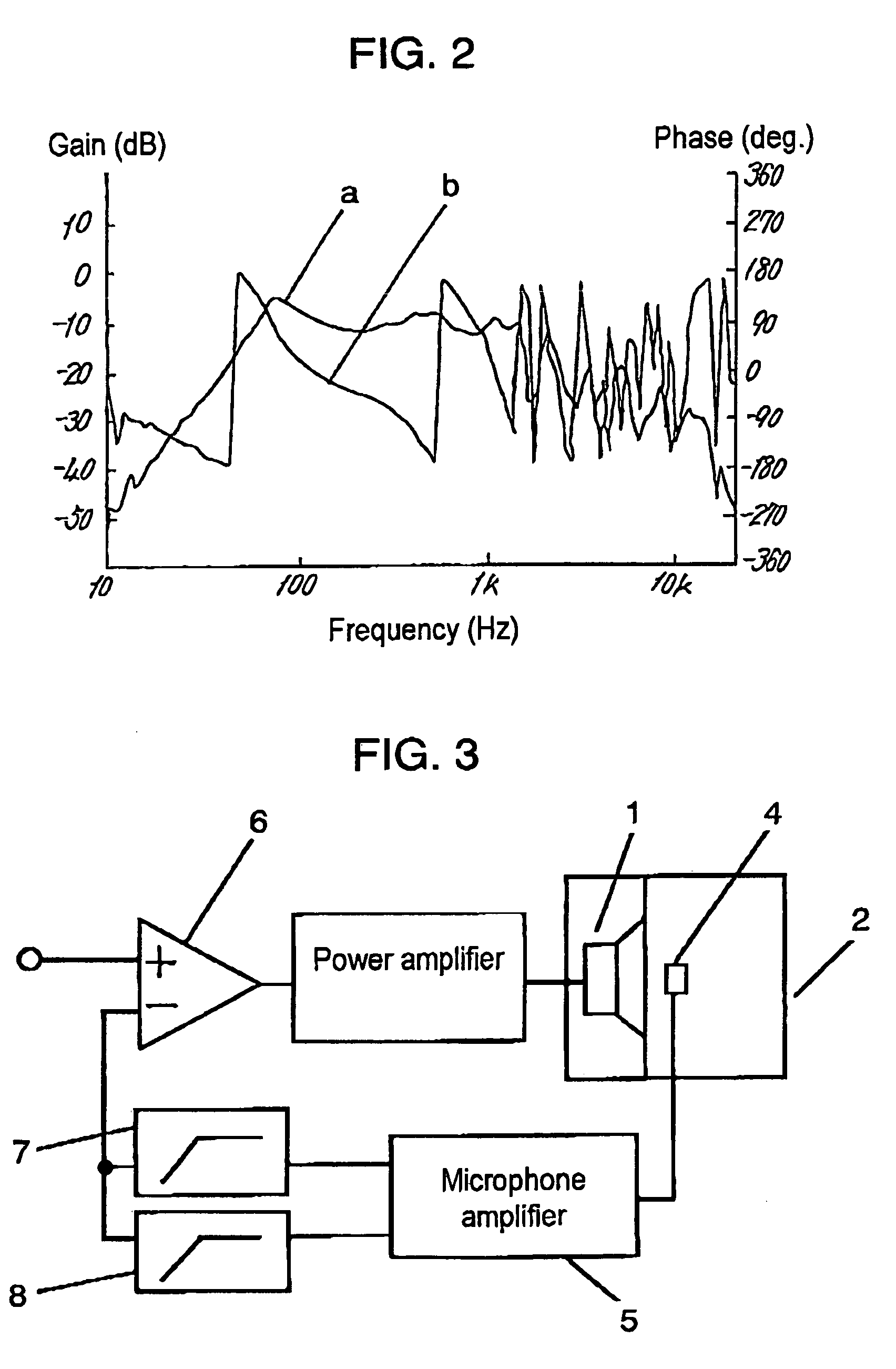
[0032]FIG. 3 shows a block diagram of a sound circuit in accordance with a second exemplary embodiment of the present invention. FIG. 4 (A) shows a microphone output signal characteristic, FIG. 4 (B) shows acoustic output characteristics, where, curve “a” shows a sound pressure characteristic, while curve “b” shows a phase characteristic. A difference compared to the first embodiment is that a negative feedback circuit in the present embodiment is formed by delivering the acoustic output signals detected by microphone 4 to the subtracter 6 via a couple of high-pass filters 7 and 8 connected in parallel. The filter 7 is the secondary high-pass filter (−12 dB / oct), while the filter 8 is the primary high-pass filter (6 dB / oct).

[0033]According to FIG. 8 (A), which shows the frequency characteristic of the microphone signal of the conventional device, the feedback is performed covering even the low frequency region components, which means the low frequency region components are enhanced....

third embodiment

[0036]FIG. 5 shows a block diagram of a sound circuit in accordance with a third exemplary embodiment of the present invention. FIG. 6 (A) shows the microphone output signal characteristics, FIG. 6 (B) shows the sound output characteristics, where, curve “a” shows the sound pressure characteristic, while curve “b” shows the phase characteristic. A difference compared to the first embodiment is that a negative feedback circuit in the present embodiment is formed of a couple of filters 7 and 9. A secondary high-pass filter 7 for processing the output signal detected by the microphone 4 and delivering to the subtracter 6, and a low-pass filter 9 of −12 dB / oct, or −6 dB / oct, for processing the output signal detected by the microphone 4 and delivering to the subtracter 6.

[0037]The low-pass filter 9 can take out only the low frequency region components for phase correction. Thus, the output sound characteristic can be corrected for the low frequency region components alone. The secondary ...


PUM


Abstract

A loudspeaker device comprising a power amplifier (13) to which an input signal is delivered via a subtracter (6), a speaker unit (1) for reproducing output signals delivered from the power amplifier (13), an acoustic pipe (2) coupled in front of the speaker unit for guiding the sound waves, a microphone (4) for detecting an acoustic outputs radiated from the speaker unit, a microphone amplifier (5) for amplifying an acoustic output signals detected by the microphone, and a negative feedback circuit. Output signals of the microphone amplifier are delivered to the subtracter, at the same time the same output signal is connected to a high-pass filter (7) to be delivered to the subtracter. Thus the negative feedback circuit is formed to suppress peaks and dips for providing a flattened sound pressure frequency characteristic.

Description

FIELD OF THE INVENTION[0001]The present invention relates to a loudspeaker (speaker) device for use in various acoustic apparatus and television receivers; more specifically, a speaker unit coupled with an acoustic pipe disposed in front of the speaker, wherein the acoustic pipe has a microphone for detecting sounds reproduced by the speaker unit, and sounds from the speaker unit are corrected in accordance with the signals detected by the microphone.BACKGROUND OF THE INVENTION[0002]A conventional speaker device of the same type is described with reference to FIG. 7, FIG. 8 (A) and FIG. 8 (B). FIG. 7 is a block diagram, FIG. 8 (A) shows microphone output signals, FIG. 8 (B) shows sound output characteristics of the conventional speaker device, where, curve “a” shows a sound pressure characteristic, and curve “b” shows a phase characteristic.[0003]Referring to FIG. 7, a speaker unit 1 generates sound waves, and the speaker unit 1 is coupled with an acoustic pipe 2. At both sides of t...

Claims


Application Information

Patent Timeline
Patent Type & Authority Patents(United States)
IPC IPC(8): H04R3/00H04B15/00H04R27/00H04R29/00H04R1/02H04R3/04
CPCH04R3/02H04R3/002
Inventor TANAKA, HIDEKAZUKONNO, FUMIYASU
Owner PANASONIC CORP
Why Eureka
Try Eureka