
Lighting apparatus

a technology of lighting apparatus and light bulb, which is applied in the field of lighting apparatus, can solve the problems of reducing the quantity of light, wasting the lighting time, so as to reduce the number of wirings, simplify the construction, and enhance the general purposability.

Inactive Publication Date: 2006-11-14
TDK CORPARATION
View PDF19 Cites 26 Cited by
  • Summary
  • Abstract
  • Description
  • Claims
  • Application Information

AI Technical Summary

Benefits of technology

The present invention provides a lighting unit and apparatus that allows for easy detachment and attachment of light emitting diodes and other lighting elements from a camera or other object. The lighting unit includes a light emitting diode case, a temperature control element, and a heat radiating member, which are all independently fixed to the object. A fixing member is used to bring the lighting unit into tight contact with the object. The lighting apparatus can be used as a dedicated lighting apparatus for different objects and can control the temperature of the object. The lighting unit is easy to install and remove, and the construction is simplified.

Problems solved by technology

More specifically, the LED has a problem that when the temperature thereof rises, the quantity of light thereof decreases, and, for example, after the quantity of light becomes temporarily stable after the LED has been turned ON, the temperature rises with a lapse of the lighting time to decrease the quantity of light.
However, for example, in the case where an electronic component is inspected for mounting state, when the electronic component, the mounting board, and the like are further miniaturized, and also the color tones or the like in their materials become close to each other, the above-mentioned change in lighting state may become unable to be disregarded.
It is conceivable that such a request will become more and more severe in the future along with the miniaturization and promotion of high performance of the electronic components.
In addition, it is also supposed that when the camera and the lighting apparatus are miniaturized and the camera and the lighting apparatus are then tried to be easily detached from and attached to each other, the disposition itself of a temperature measurement device within the lighting apparatus becomes difficult.
However, when a lighting apparatus constituted by a plurality of LEDs each having high directivity is used as a light source, it is normally difficult to move a focal point of the lighting apparatus.
Hence, it is judged that in actual, this lighting apparatus will require a complicated wiring and the like.
Consequently, when any one of the lighting apparatuses disclosed in the above-mentioned Patent Documents is tried to be installed in an actual camera, it is judged to be difficult to carry out an operation for the installation readily and speedily.
Thus, for example, it is judged that this construction is not suitable for a situation in which an LED is frequently exchanged for another one.
In addition, with the constructions disclosed in the above-mentioned Patent Documents, it is judged to be difficult to reduce a change in temperature which is generated in a camera or the like having the LEDs fixed thereto due to the fixing of the LEDs or the like.

Method used


Image

  • Lighting apparatus
  • Lighting apparatus
  • Lighting apparatus

Examples


Embodiment Construction

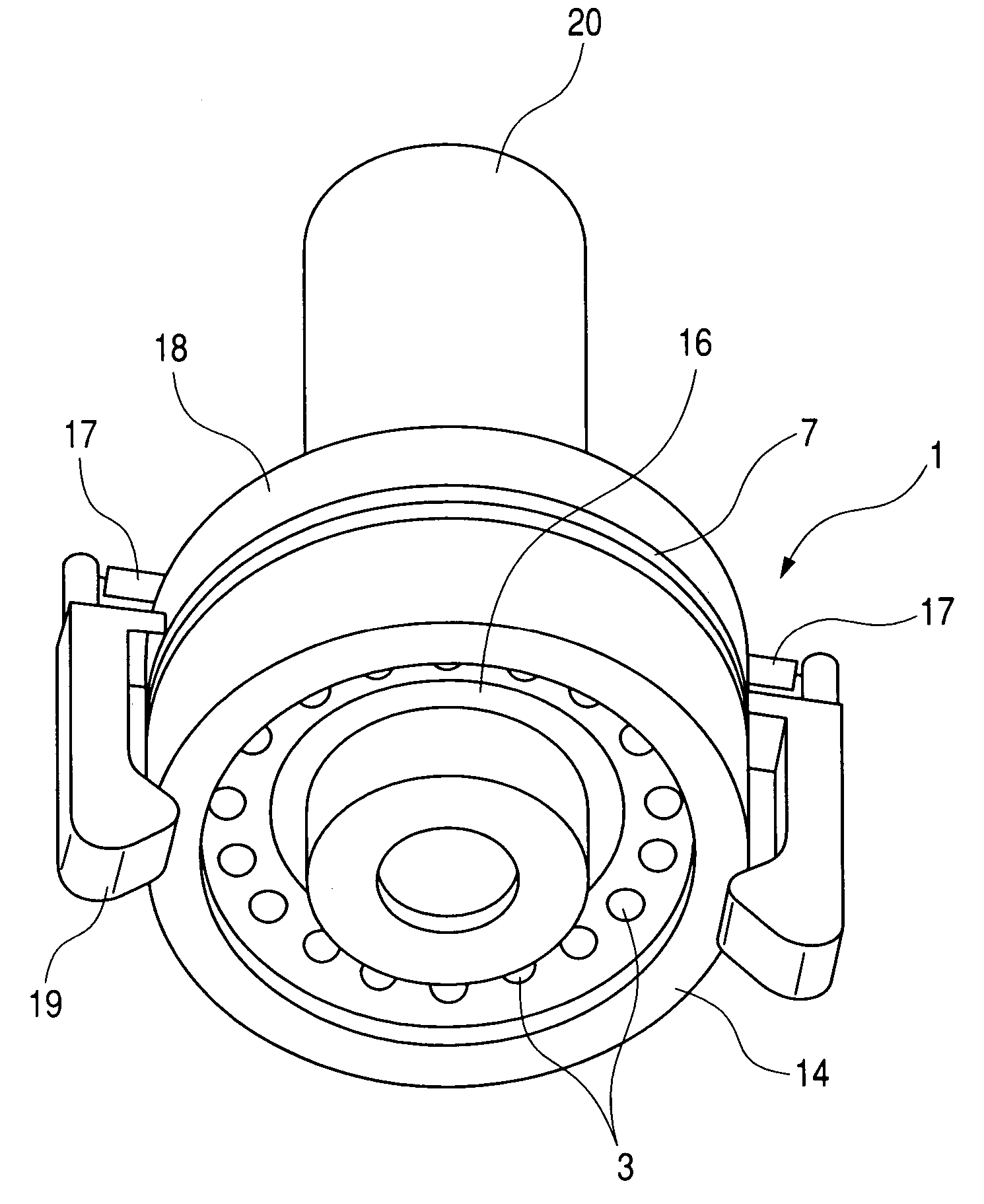
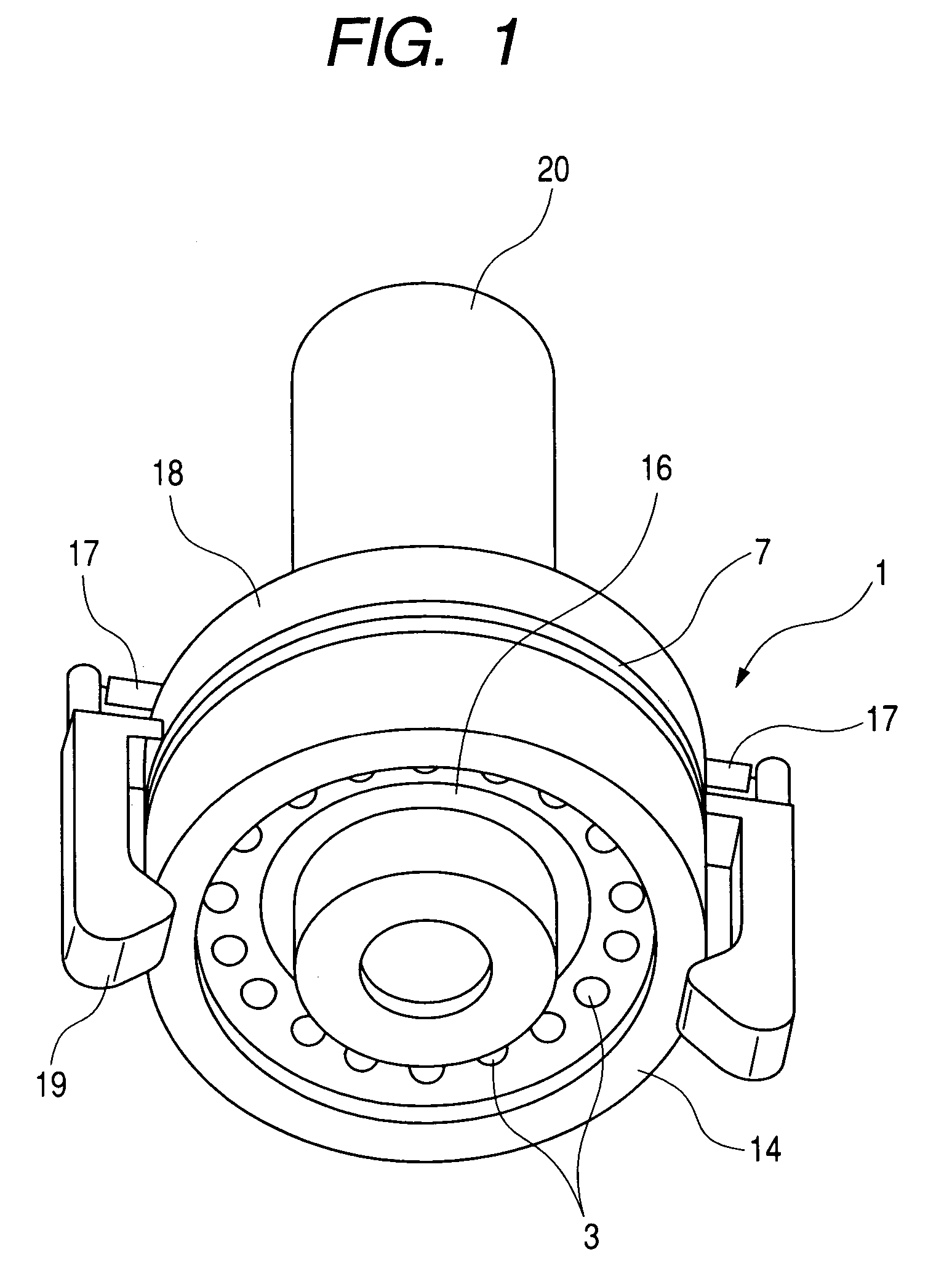
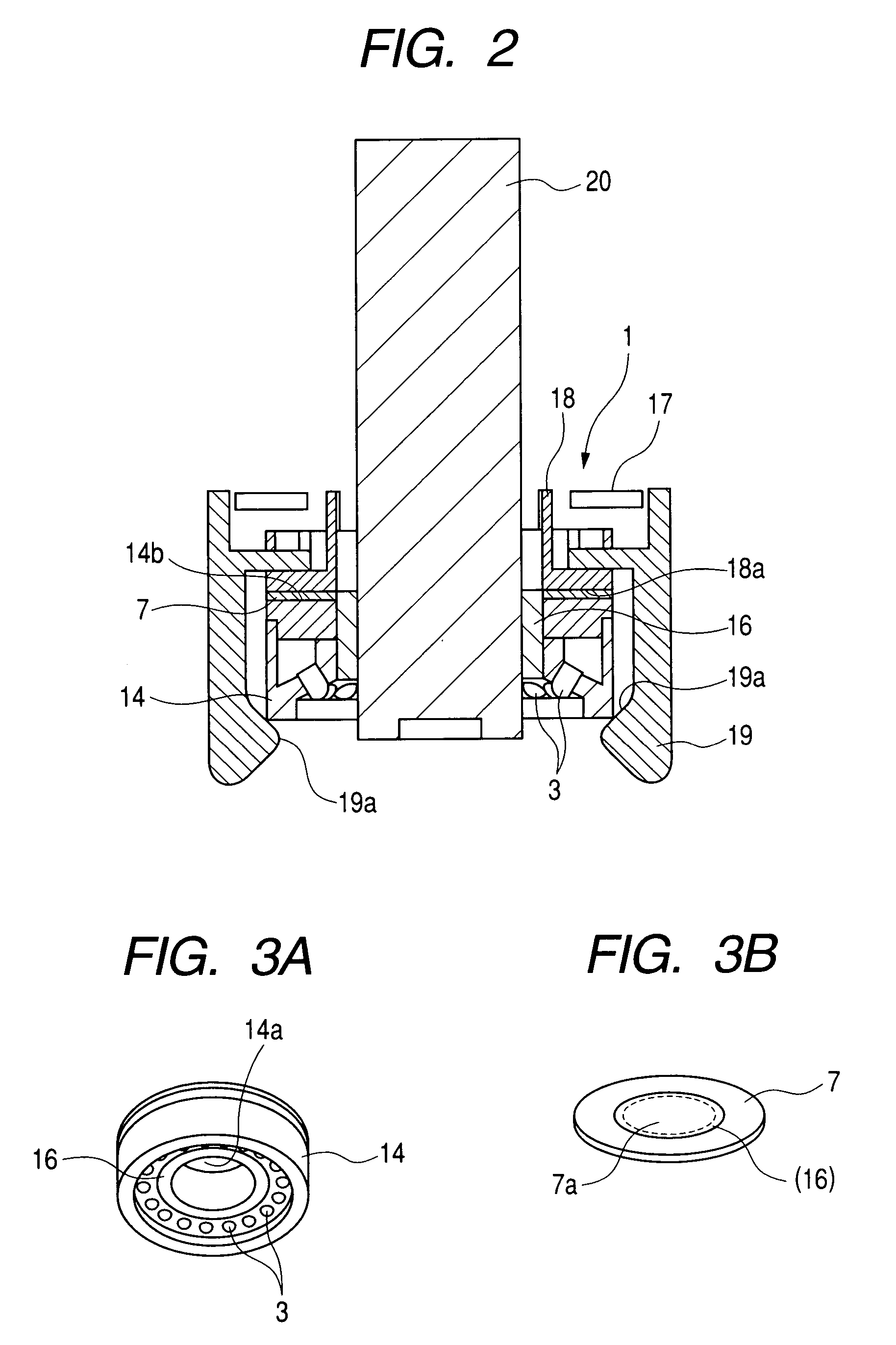
[0027]A preferred embodiment using a lighting apparatus according to the present invention will hereinafter be described in detail with reference to the accompanying drawings. FIG. 1 is a schematic perspective view in a state in which a lighting apparatus according to the present invention is constructed in the form of a unit to be installed in a camera. FIG. 2 shows a schematic cross section of the construction shown in FIG. 1. The lighting apparatus 1 has a nearly ring like shape, and a camera 20 is inserted into a through hole portion (accommodation space) of the lighting apparatus 1. In addition, the lighting apparatus 1 has a ring like light emitting diode (LED) case 14 to which a plurality of LEDs 3 are fixed so as to be directed downwardly, and a ring like Peltier element 7 brought into tight contact with a rear surface of the LED case 14.

[0028]A cylindrical thermal transfer member 16 which is also brought into tight contact with the Peltier element 7 is tightly fixed to an i...


PUM

PropertyMeasurementUnit
temperatureaaaaaaaaaa
angleaaaaaaaaaa
luminous intensityaaaaaaaaaa

Abstract

The present invention aims at providing a lighting apparatus which is to be installed in a color camera, which is capable of providing the stable quantity of light from a light source such as an LED, and which is capable of stabilizing color tones of an image captured with the color camera. In order to attain this object, in the lighting apparatus according to the present invention, the temperature control for the camera is also simultaneously carried out using a thermal transfer member for enhancing heat transfer between a Peltier element used for the temperature control for an LED case with built-in LEDs, and the LED case.

Description

BACKGROUND OF THE INVENTION[0001]1. Field of the Invention[0002]The present invention relates in general to a lighting apparatus constituted by light emitting elements such as light emitting diodes. In particular, the present invention relates to a lighting apparatus which has such a simple construction as to be easily detached from and attached to a camera or the like, and which is capable of providing a stable luminous intensity independently of a change in temperature of light emitting elements.[0003]2. Related Background Art[0004]For example, there is known an inspection apparatus for photographing an object of inspection using a camera to carry out the quality control of the object based on the photography results. In such an inspection apparatus, in order to make an image of the object clearer, a lighting apparatus for lighting up an object is also simultaneously used. For this lighting apparatus, there is used one having a plurality of light emitting diodes (hereinafter refer...

Claims


Application Information

Patent Timeline
Patent Type & Authority Patents(United States)
IPC IPC(8): G03B15/03H04N5/222G01N21/84F21S2/00F21S8/04F21V29/00F21V29/02F21Y101/02F25B21/02G01N21/88G03B15/00G03B15/02G03B15/05G03B15/06G03B17/02G03B17/56H01L33/00H04N5/225
CPCG01N21/8806G03B15/05F21Y2101/02G03B2215/0539F21Y2115/10
Inventor HAYAMI, KENICHIKANEKO, MASAAKI
Owner TDK CORPARATION
Learn More