Multiple processor system and method including multiple memory hub modules

a multi-processor and memory hub technology, applied in the field of computer systems, can solve the problems of reducing the data bandwidth of the processor, the inability to maintain the operation speed of the processor, and the inability to meet the requirements of the processor

Inactive Publication Date: 2006-11-14
ROUND ROCK RES LLC
View PDF234 Cites 68 Cited by
  • Summary
  • Abstract
  • Description
  • Claims
  • Application Information

AI Technical Summary

Benefits of technology

[0011]There is therefore a need for a memory system architecture that is relatively fault-intolerant, that provides relatively low latency memory accesses, an that allows multiple processor to have a great deal of flexibility in the manner in which they access hub-based memory modules.

Problems solved by technology

Although the operating speed of memory devices has continuously increased, this increase in operating speed has not kept pace with increases in the operating speed of processors.
As a result, the data bandwidth between a processor and memory devices to which it is coupled is significantly lower than the data bandwidth capabilities of the processor.
The data bandwidth between the processor and memory devices is limited to a greater degree by the even lower data bandwidth between the processor and the memory devices.
In addition to the limited bandwidth between processors and memory devices, the performance of computer systems is also limited by latency problems that increase the time required to read data from the memory devices.
Therefore, although SDRAM devices can synchronously output burst data at a high data rate, the delay in initially providing the data can significantly slow the operating speed of a computer system using such SDRAM devices.
However, they nevertheless suffer from several limitations.
For example, the architecture shown in FIG. 1 does not provide a great deal of flexibility in the manner in which the processor 14 can access the memory modules 20a–f.
The flexibility of the architectures shown in FIGS. 1 and 3 are also limited in other respects.
Insofar as each memory module is accessed through any memory module that is between it and the processor, substantial delays may be incurred in coupling address, data and control signals through the intervening memory modules.

Method used


Image

  • Multiple processor system and method including multiple memory hub modules
  • Multiple processor system and method including multiple memory hub modules
  • Multiple processor system and method including multiple memory hub modules

Examples


Embodiment Construction

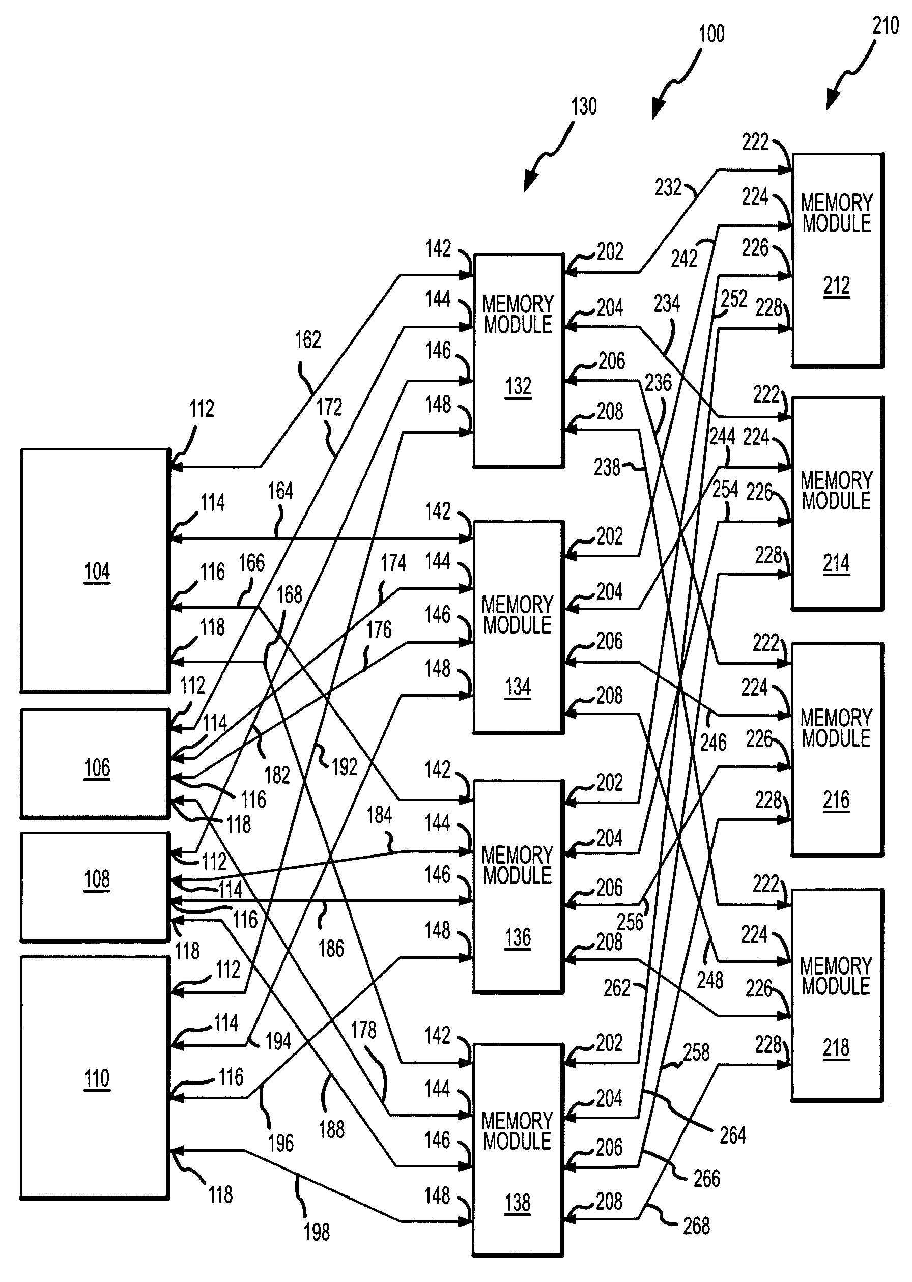
[0019]A processor-based electronic system 100 according to one example of the invention is shown in FIG. 4. The system 100 includes three processors 104, 106, 108 and a direct memory access (“DMA”) device 110, such as a graphics controller. The DMA device 110 and each of the processors 104–108 includes four memory access ports 112, 114, 116, 118. The ports 112–118 preferably include a data port as well as either individual or a shared control and address ports. However, it will be understood that some other memory port configuration may be used, such as a port for receiving and transmitting packets. The system 100 also includes a first rank 130 of four memory modules 132, 134, 136, 138 each of which includes a first set of four memory access ports 142, 144, 146, 148. As explained below, each of the memory modules 132–138 includes a memory hub coupled to eight memory devices, which are preferably dynamic random access memory (“DRAM”) devices, and, more preferably, synchronous DRAM (“...


PUM


Abstract

A processor-based electronic system includes several memory modules arranged in first and second ranks. The memory modules in the first rank are directly accessed by any of several processors, and the memory modules in the second rank are accessed by the processors through the memory modules in the first rank. The data bandwidth between the processors and the memory modules in the second rank is varied by varying the number of memory modules in the first rank that are used to access the memory module in the second set. Each of the memory modules includes several memory devices coupled to a memory hub. The memory hub includes a memory controller coupled to each memory device, a link interface coupled to a respective processor or memory module, and a cross bar switch coupling any of the memory controllers to any of the link interfaces.

Description

TECHNICAL FIELD[0001]This invention relates to computer systems, and, more particularly, to a computer system having several processors or other memory access devices that can be coupled to several memory hub modules in a variety of configurations.BACKGROUND OF THE INVENTION[0002]Computer systems use memory devices, such as dynamic random access memory (“DRAM”) devices, to store instructions and data that are accessed by a processor. These memory devices are normally used as system memory in a computer system. In a typical computer system, the processor communicates with the system memory through a processor bus and a memory controller. The processor issues a memory request, which includes a memory command, such as a read command, and an address designating the location from which data or instructions are to be read or to which data or instructions are to be written. The memory controller uses the command and address to generate appropriate command signals as well as row and column ...

Claims


Application Information

Patent Timeline
Patent Type & Authority Patents(United States)
IPC IPC(8): G06F13/00G06F12/08G06FG11C5/00
CPCG11C5/00G06F12/0862G06F13/4022G06F13/00G06F13/14
Inventor JEDDELOH, JOSEPH M.
Owner ROUND ROCK RES LLC
Why Eureka
Try Eureka