Pattern factor control valve

a technology of pattern factor and control valve, which is applied in the direction of valve operating means/releasing devices, turbine/propulsion fuel valves, mechanical equipment, etc., can solve the problems of unstable burning, unstable burning, and unstable combustion, and achieve high accuracy and responsive fuel

a technology of pattern factor and control valve, which is applied in the direction of valve operating means/releasing devices, turbine/propulsion fuel valves, mechanical equipment, etc., can solve the problems of unstable burning, unstable burning, and unstable combustion, and achieve high accuracy and responsive fuel

US7137613B2Inactive Publication Date: 2006-11-21JANSENS AIRCRAFT SYST CONTROLS

Image

  • Pattern factor control valve
  • Pattern factor control valve
  • Pattern factor control valve

Examples


Embodiment Construction

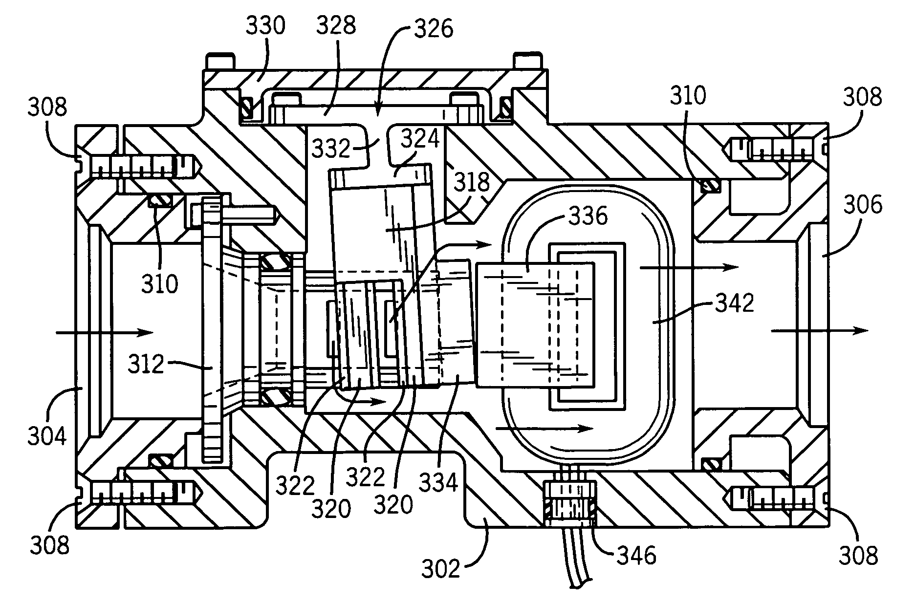
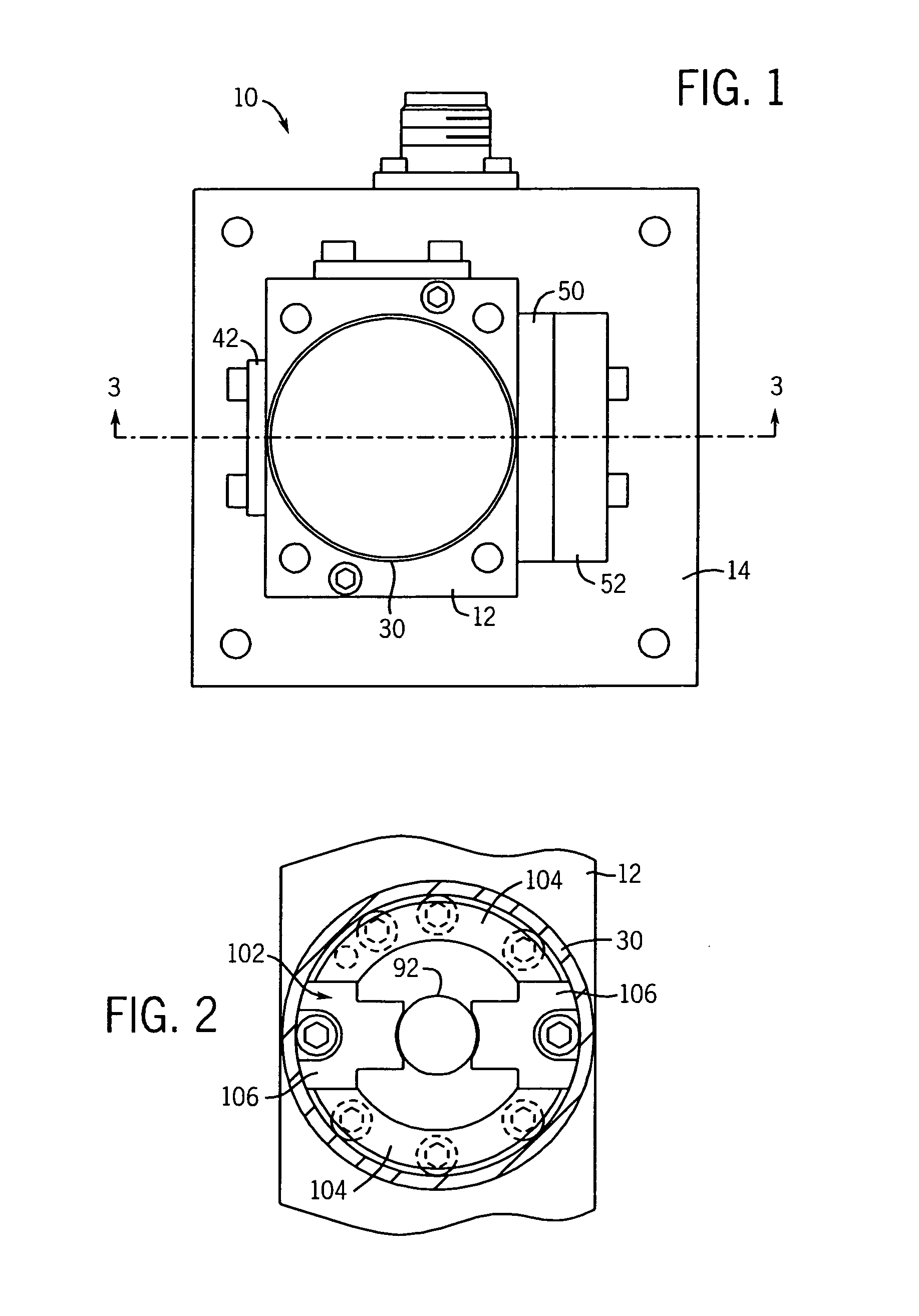
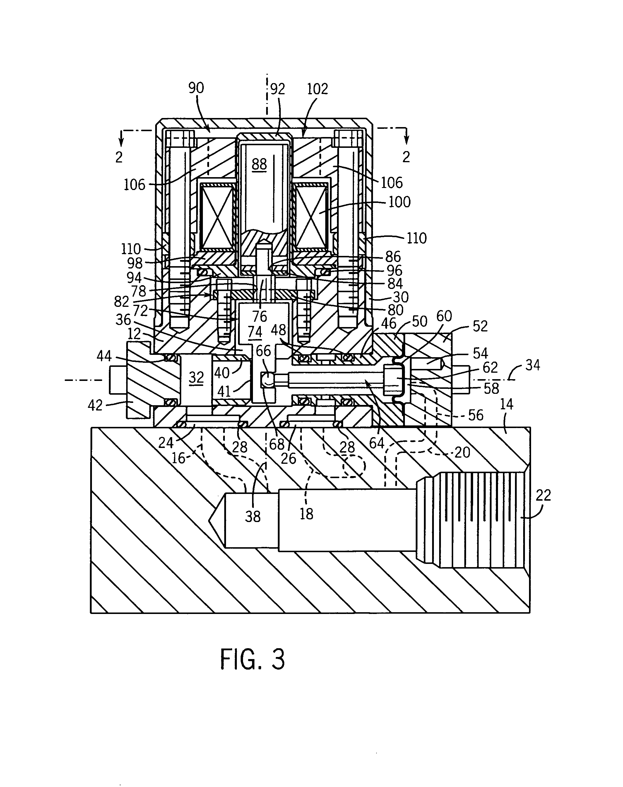
[0035]The present invention provides a high flow volume and flow rate fuel metering valve having attributes designed to make it highly responsive to input drive signals, for example having low weight, pressure balanced actuating components with low damping, low drag and bluff body forces and low hysteresis, such that is suitable to operate in high rate gas turbine combustion control systems designed to stabilize the combustion process of the burners. Disclosed herein are two preferred embodiments of an active combustion control valve and a preferred embodiment of a pattern factor control valve according to the present invention. The first embodiment utilizes a flapper valve member that is pressure balanced by a rolling diaphragm piston. The second embodiment described uses an inherently balanced bridged clevis to simultaneously control metering through multiple metering orifices (four in the described valve). The pattern factor control valve described herein uses a similar clevis va...


PUM


Abstract

A fuel valve for use in regulating the pattern factor of a gas turbine has a highly accurate pressure balanced clevis valve assembly. The clevis valve is pivotally mounted inside the valve housing by a flexure pivot, and has a pair of legs at each side of a valve body that control flow through pairs of flow orifices. An armature mounts to the clevis valve, and when energized, an electromagnet inside the valve housing generates magnetic flux that moves the armature to pivot the clevis valve to open or closed the orifices. The clevis valve is inherently balanced and can meter fuel through multiple orifices simultaneously.

Description

CROSS-REFERENCE TO RELATED APPLICATIONS[0001]This application claims benefit to U.S. provisional application Ser. No. 60 / 625,298, filed Nov. 5, 2004, and is a continuation-in-part application of U.S. application Ser. No. 11 / 149,870, filed Jun. 10, 2005, now U.S. Pat. No. 7,004,449, which is a divisional application of U.S. application Ser. No. 10 / 377,979, filed Feb. 28, 2003, now U.S. Pat. No. 6,918,569, which claims benefit to U.S. provisional application Ser. No. 60 / 361,446 filed Feb. 28, 2002.STATEMENT OF FEDERALLY SPONSORED RESEARCH OR DEVELOPMENT[0002]Not applicable.BACKGROUND OF THE INVENTION[0003]1. Technical Field[0004]The present invention relates to fuel valves, and in particular, to highly accurate valves suitable for use in regulating fuel to the burners of turbine engine systems.[0005]2. Description of the Related Art[0006]Modern gas turbines used in the generation of power typically employ various lean fuel / air mixing techniques, largely to reduce the levels of harmful...

Claims


Application Information

Patent Timeline
21 Nov 2006
Publication
US7137613B2
IPC
F16K31/10; F02C9/26
CPC
F02C7/232; F16K31/10
Inventors
JANSEN, HARVEY B.