Electrically movable vehicle and control program for driving electrically movable vehicle

a technology of electrically movable vehicles and control programs, which is applied in the direction of electronic commutators, motor/generator/converter stoppers, dynamo-electric converter control, etc., can solve the problems of complex structure of control programs, and achieve simple control modes, high stability, and high mobility

Inactive Publication Date: 2006-11-21
SANYO ELECTRIC CO LTD
View PDF5 Cites 10 Cited by
  • Summary
  • Abstract
  • Description
  • Claims
  • Application Information

AI Technical Summary

Benefits of technology

[0007]According to the invention, the velocity command value calculating unit determines one of the velocity command value for the translation of the vehicle and the velocity command value for the turning motion thereof from the command value obtained by the input unit. The velocity command value calculating unit calculates and determines the other velocity command value from a detected velocity corresponding to the velocity command value determined. Thus, after one of the velocity command values has been determined, the velocity command value for the other motion is determined so as to satisfy the stabilizing condition. Accordingly, a translation velocity command value and a turning motion velocity command value can be determined efficiently which will satisfy the stabilizing condition, for example, for preventing the vehicle from falling down due to a centrifugal force. This realizes the control of the vehicle with a simplified program unlike the case wherein judgment is made as to whether the stabilizing condition can be satisfied after the two motion velocities have been determined.
[0019]According to the invention, the electrically movable vehicle can be driven with high stability and high mobility by a simple mode of control.

Problems solved by technology

Accordingly, the control program becomes complex in structure due to increased number of condition judging steps and a specific processing procedure required for the value of the command input unit.

Method used


Image

  • Electrically movable vehicle and control program for driving electrically movable vehicle
  • Electrically movable vehicle and control program for driving electrically movable vehicle
  • Electrically movable vehicle and control program for driving electrically movable vehicle

Examples


embodiment 1

[0063]Next, Embodiment 1 wherein the construction described above is used will be described with reference to FIGS. 5 to 7.

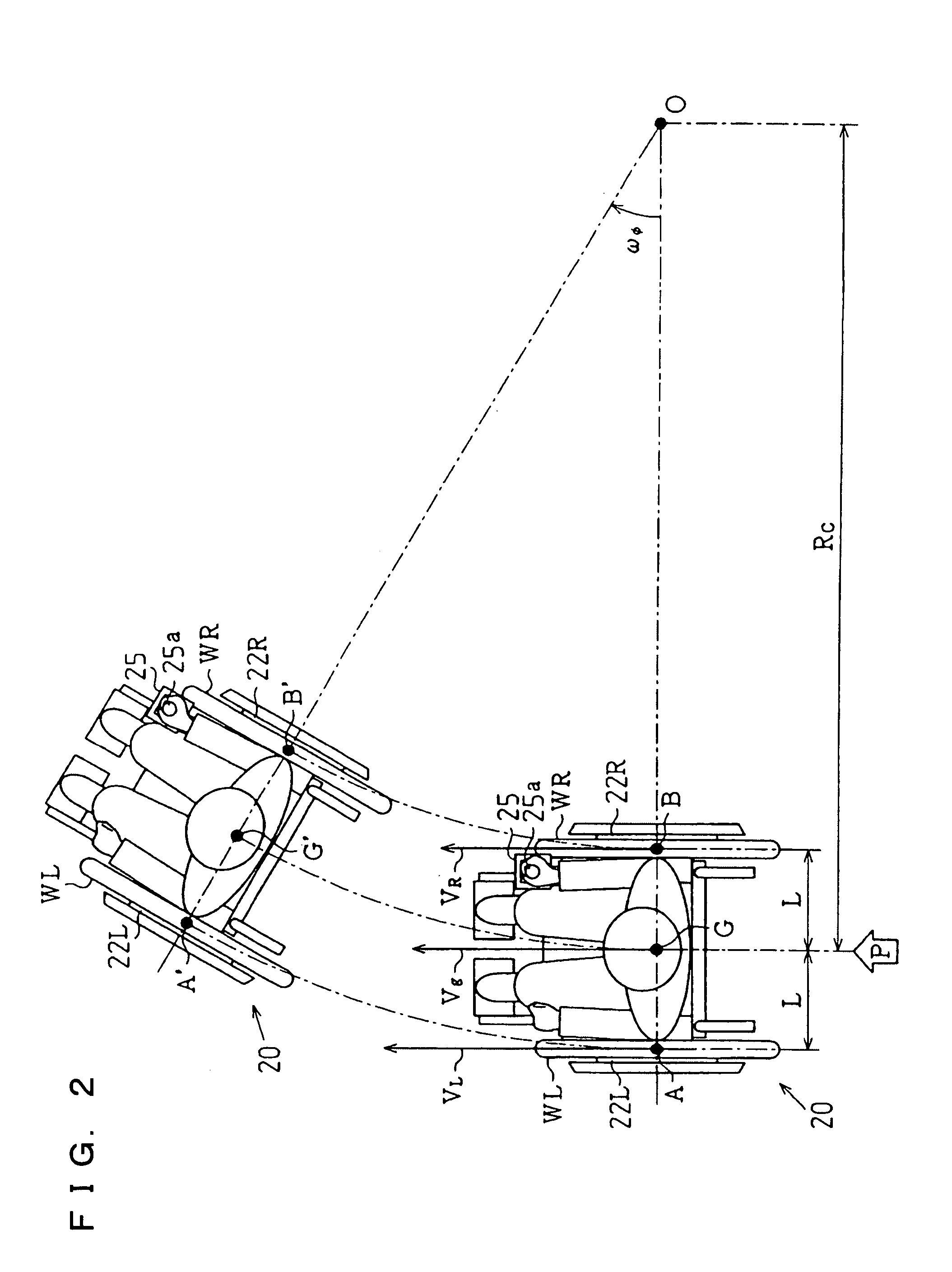
[0064]In Embodiment 1, a translation velocity command value Vg—trg for translation motion is determined using a command input value in y-direction which is the direction of straight advance. Further in Embodiment 1, a command value of turn angular velocity about the center of gravity G, ωf—trg, is also determined from a command input value in the x-direction which is the turn direction and the translation direction velocity Vg of the center of gravity G of the wheelchair 20.

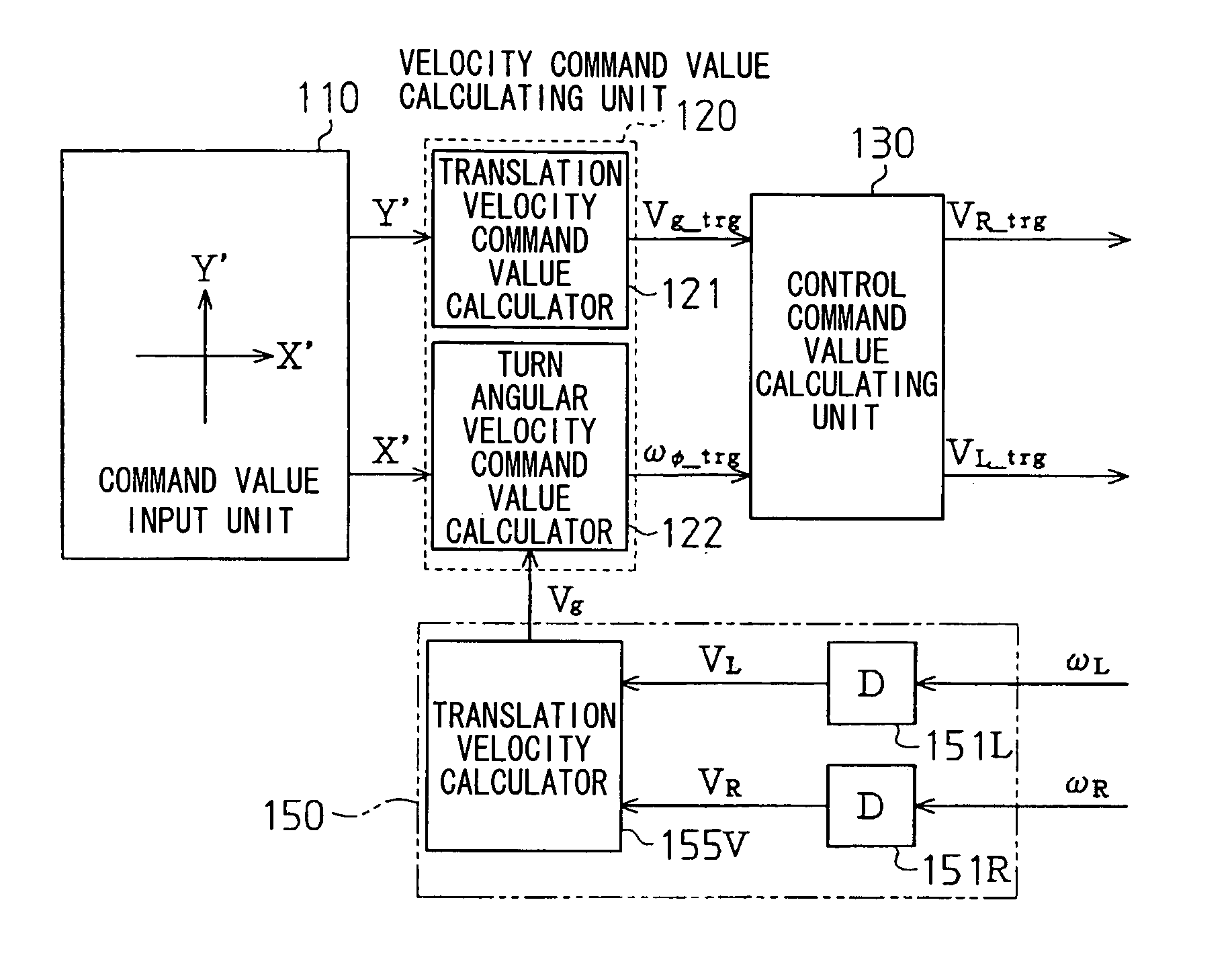
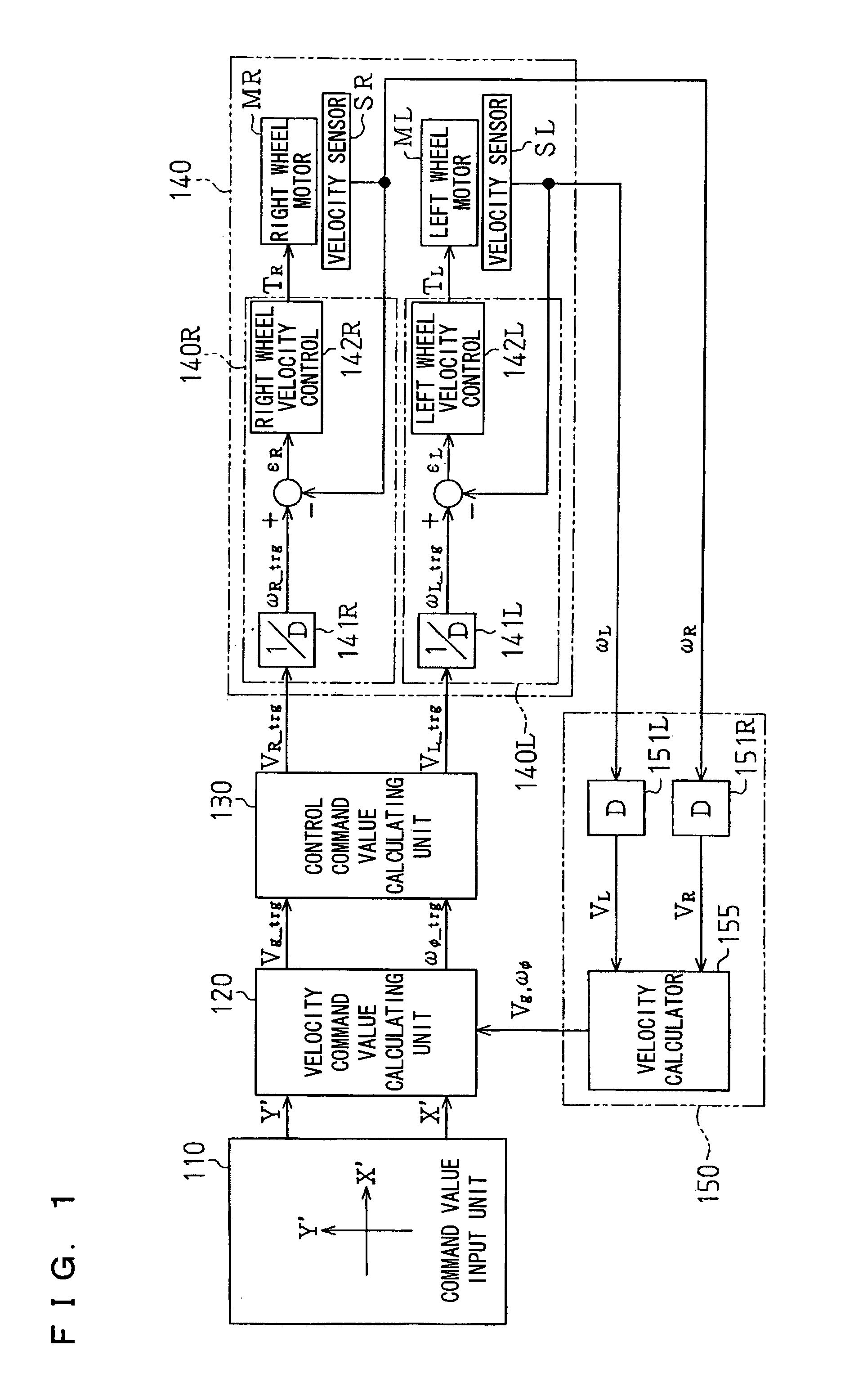
[0065]According to the present embodiment, the velocity command value calculating unit 120 comprises a translation velocity command value calculator 121 and a turn angular velocity command value calculator 122 as shown in FIG. 6.

[0066]The translation velocity command value calculator 121 calculates the command value Vg—trg of translation velocity at the center of gravity G.

[0067]Stated more s...

embodiment 2

[0087]Next, Embodiment 2 wherein the construction described above is used will be described with reference to FIGS. 8 to 10.

[0088]In Embodiment 2, a turn angular velocity command value ωf—trg for turning motion is determined using a command input value in x-direction which is the turning direction. Further in Embodiment 2, a translation velocity command value Vg—trg at the center of gravity G is also determined from a command input value in the y-direction which is the straight advance direction and the turn angular velocity ωf about the center of gravity G of the wheelchair 20.

[0089]According to the present embodiment, the velocity command value calculating unit 120 comprises a turn angular velocity command value calculator 122′ and a translation velocity command value calculator 121′ as shown in FIG. 9.

[0090]The turn angular velocity command value calculator 122′ calculates the command value of turn angular velocity ωf—trg about the center of gravity G. More specifically, the calc...

embodiment 3

[0102]Next, Embodiment 3 will be described with reference to FIGS. 11 to 13.

[0103]According to Embodiment 3, a low-pass filter unit 115 is provided between the command value input unit 110 and the velocity command value calculating unit 120 as shown in FIG. 11. The filter unit 115 has first and second low-pass filters LPF1, LPF2. With reference to FIG. 12 showing the gain-frequency characteristics of these filters, these filters are each a filter serving as a first-order lag element of F(s)=s / (s+s) wherein s is the Laplacean operator, and s is the corner frequency.

[0104]To the first low-pass filter LPF1 is input the x-direction command input normalized value X′ output from the command value input unit 110. An X-direction command input normalized value X″ are output anew from the first low-pass filter LPF1.

[0105]The y-direction command input normalized value Y′ output from the command value input unit 110 is input to the second low-pass filter LPF2. Output anew from the second low-pa...


PUM


Abstract

The invention provides an electrically movable vehicle drivable by a simplified mode of control and a control program for driving the vehicle. A normalized value Y′ representing translation motion and a normalized value X′ representing turning motion are fed from a command value input unit 110 to a velocity command value calculating unit 120. The calculating unit 120 determines a translation velocity command value Vg<sub2>—< / sub2>trg based on the normalized value Y′. The calculating unit 120 determines a turn angular velocity command value ωf<sub2>—< / sub2>trg that will always satisfy Expression (2–4) for preventing the vehicle from falling down. The translation velocity command value Vg<sub2>—< / sub2>trg and the turn angular velocity command value ωf<sub2>—< / sub2>trg determined by the unit 120 are fed to a control command value calculating unit 130, which calculates control command values for left and right drive wheels. The control command values are fed to a motor control unit 140 to control motors Mr, Ml and control the drive wheels.

Description

FIELD OF THE INVENTION[0001]The present invention relates to electrically movable vehicles which can be manipulated, for example, by the rider for controlling the motion of the vehicle using direction command means and to control programs for driving the electrically movable vehicle.BACKGROUND OF THE INVENTION[0002]Maneuverability is important with electrically movable vehicles such as wheelchairs. Accordingly, techniques are disclosed as to electrically movable vehicles which realize maneuverability approximate to turning as imaged by the user (see, for example, the publication of JP-A No. 2001-104396, page 1). The electrically movable vehicle disclosed in the patent literature is driven by controlling the operation of a first motor for driving the right wheel and a second motor for driving the left wheel by a controller according to the manipulation of a joystick lever. Stated more specifically, use is made of the angle of inclination of the joystick lever and the direction of inc...

Claims


Application Information

Patent Timeline
Patent Type & Authority Patents(United States)
IPC IPC(8): H02P5/46A61G5/04B62D11/04
CPCB60L15/2036B60L2200/34Y02T10/7275Y02T10/648Y02T10/646Y02T10/72Y02T10/64
Inventor NORO, TAKUYAAKAGI, TAKAYOSHI
Owner SANYO ELECTRIC CO LTD
Why Eureka
Try Eureka