Control for battery pack

a battery pack and control device technology, applied in the field of control apparatus and method of battery pack, can solve the problems of limited opportunity to update the offset quantity, inability to accurately perform offset correction, and more or less low current sensing accuracy, so as to improve the current sensing accuracy

Active Publication Date: 2006-11-21
NISSAN MOTOR CO LTD
View PDF13 Cites 40 Cited by
  • Summary
  • Abstract
  • Description
  • Claims
  • Application Information

AI Technical Summary

Benefits of technology

[0004]It is an object of the present invention to provide battery control apparatus and process devised to improve the current sensing accuracy.

Problems solved by technology

Therefore, the opportunity to update the offset quantity is limited.
In the above-mentioned system, the offset correction is not accurately performed during the normal vehicle operation, and the current sensing accuracy is more or less low.

Method used


Image

  • Control for battery pack
  • Control for battery pack
  • Control for battery pack

Examples


Embodiment Construction

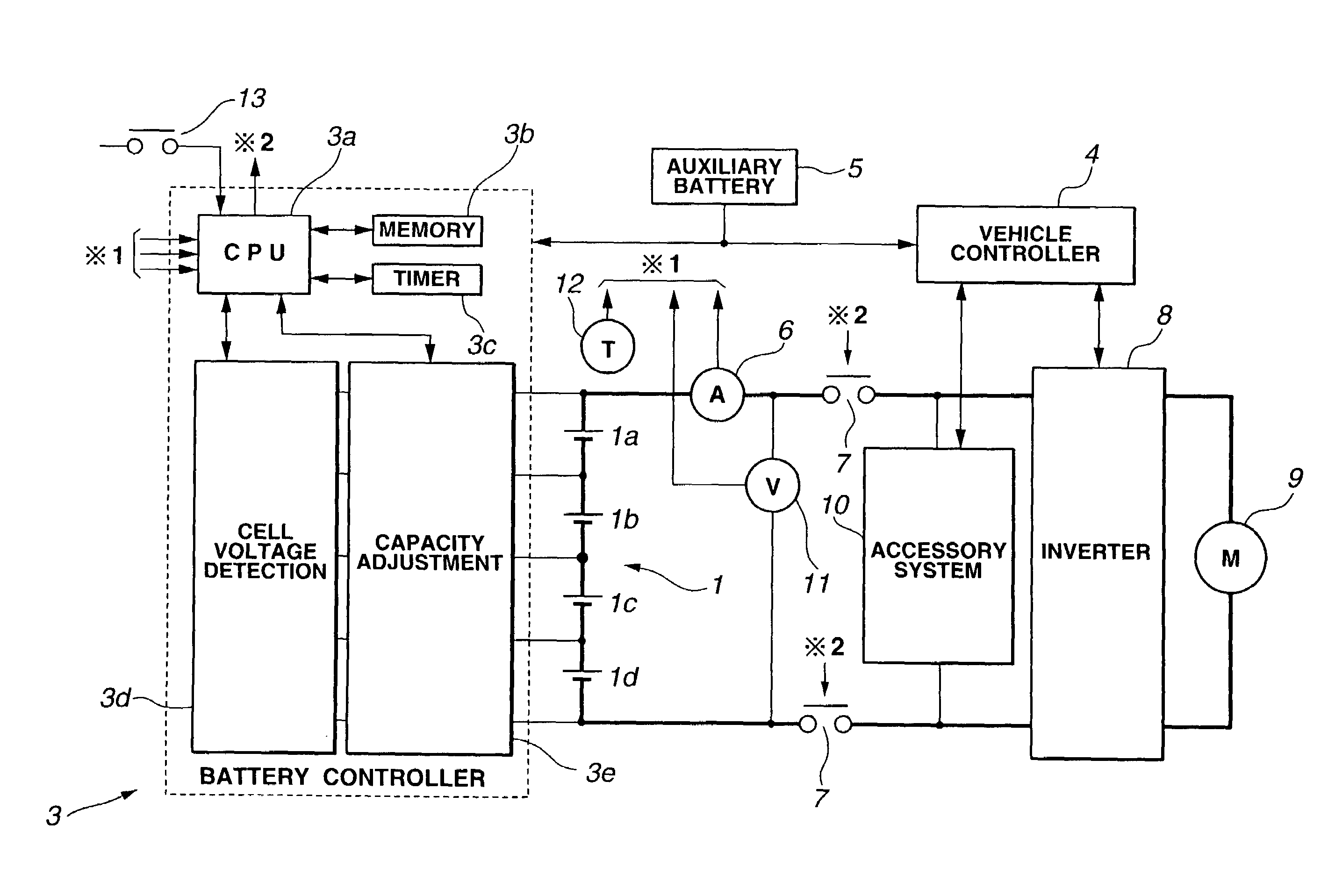
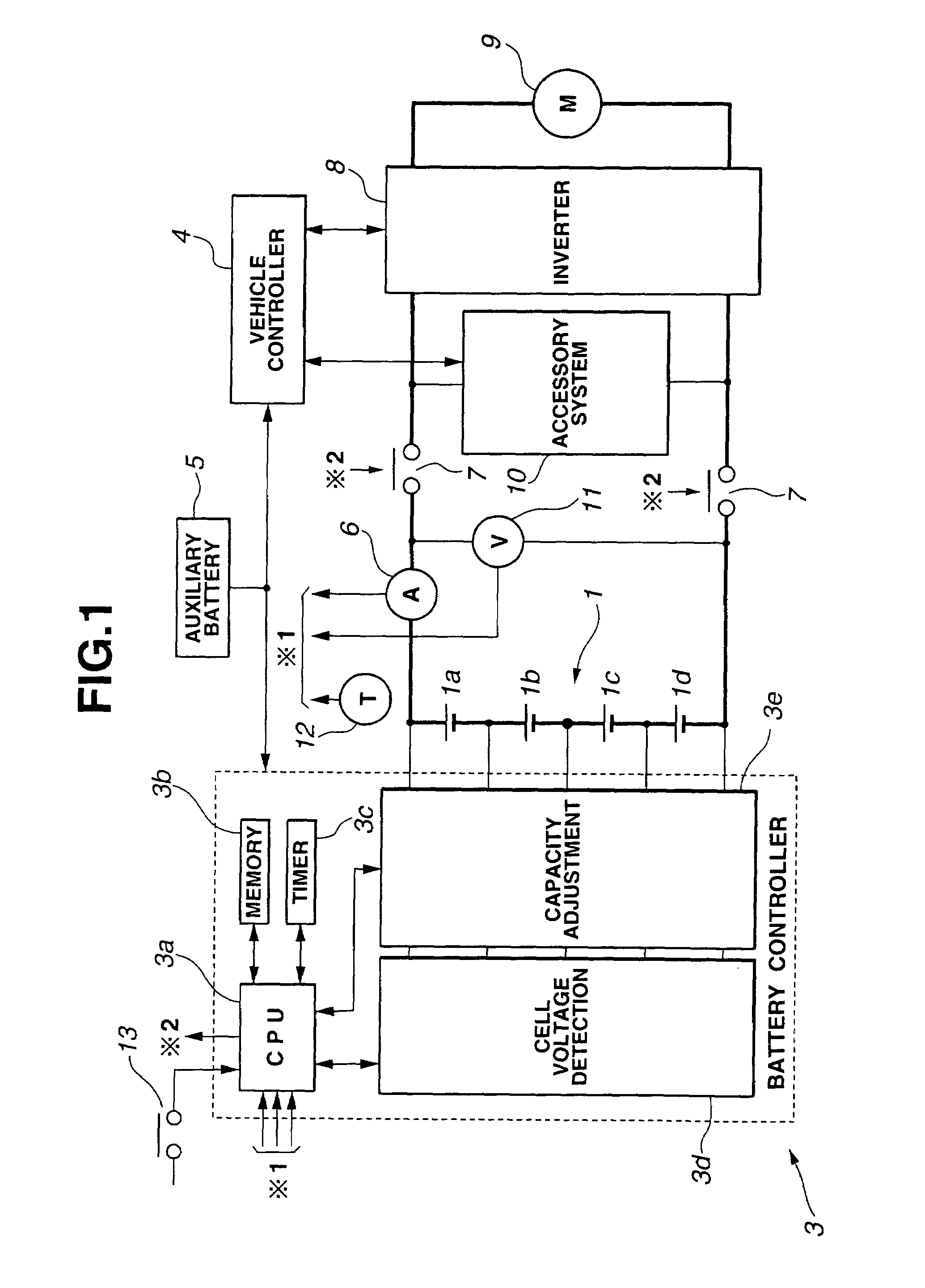
[0015]FIG. 1 shows a control system or apparatus for a battery pack for an electric vehicle (EV) according to one embodiment of the present invention. The battery pack is not limited to a battery of an electric vehicle. The battery pack which can be employed in the present invention may be a battery for a hybrid vehicle (HEV) or a battery pack of any of various other applications.

[0016]A battery pack 1 shown in FIG. 1 is a series combination of four cells 1a˜1d. Battery pack 1 is a main battery as distinguished from an auxiliary battery 5 serving as a power source for a battery controller 3 and a vehicle controller 4. The cells are four in number in the example of FIG. 1, for convenience of illustration and explanation. The number of cells connected in series in main battery 1 is not limited to four. For example, main battery 1 may include 96 cells connected in series as a main battery for an electric vehicle.

[0017]Main battery 1 may be a series-parallel circuit including a pluralit...


PUM

PropertyMeasurementUnit
cell voltage Vcaaaaaaaaaa

Abstract

A battery pack of a series combination of cell units is connected with a motor drive control circuit to drive a traction motor for a vehicle. A current sensor senses a discharge / charge current of the battery pack, and a voltage detecting circuit senses a voltage between two separate points in the series combination of the battery pack. A memory section stores a reference voltage drop quantity representing a decrease in voltage during a predetermined time interval between the two separate points. An offset detecting section compares an actual voltage drop quantity sensed by the voltage detecting circuit, with the reference voltage drop quantity, thereby detects a non-discharge / charge-current state of the current sensor, and reserves an output of the current sensor, as an offset quantity upon the detection. A correcting section corrects a sensed value of the discharge / charge current with the reserved offset quantity.

Description

BACKGROUND OF THE INVENTION[0001]The present invention relates to control apparatus and method for a battery pack for a vehicle, and more specifically to control technology to improve a current sensing accuracy.[0002]A Published Japanese Patent Application Publication No. H11(1999)-150873 shows an electric vehicle control system arranged to sense a charge / discharge current of a battery to detect the residual capacity of the battery accurately. This control system reserves an output value of a current sensor, as an offset value, when the battery is in a state free from charging and discharging, and corrects the sensed current value of the current sensor with the offset value in the normal operating state.SUMMARY OF THE INVENTION[0003]However, the control system of the above-mentioned electric vehicle control system is arranged to assume that the battery is in the non-charging / discharging state when the electric vehicle is in a rest state in which the key switch of the vehicle and a c...

Claims


Application Information

Patent Timeline
Patent Type & Authority Patents(United States)
IPC IPC(8): H02J7/00H02P7/00G01R19/00B60L3/00H01M2/10H01M6/42H01M10/42H01M10/48
CPCB60L11/1851H01M10/4257H01M10/48H02J7/0016H01M6/42Y02T10/7055Y02T10/7005Y02T10/705B60L58/10Y02T10/70Y02E60/10
Inventor SUGIMOTO, TOMONAGANAKADA, YUJIKAMISHIMA, UTAKAMORITA, TSUYOSHI
Owner NISSAN MOTOR CO LTD
Why Eureka
Try Eureka