Sensorless motor drive apparatus and method for protecting and controlling the same

a sensorless motor and drive apparatus technology, applied in the direction of motor/generator/converter stopper, dynamo-electric gear control, dynamo-electric converter control, etc., can solve the problems of reliability deterioration, increase production costs, and difficulty in ensuring the stability of the sensorless motor drive apparatus

Inactive Publication Date: 2006-11-21
LG ELECTRONICS INC
View PDF7 Cites 40 Cited by
  • Summary
  • Abstract
  • Description
  • Claims
  • Application Information

AI Technical Summary

Benefits of technology

[0018]Therefore, it is an object of the present invention to provide a sensorless motor drive apparatus for determining the presence or absence of a position estimation error of a rotor using a software method instead of using a sensor so that it prevents a motor from generating a faulty operation or prevents a compressor including the motor from being damaged, and a method for protecting and controlling the sensorless motor drive apparatus.

Problems solved by technology

If the sensor is mounted to the motor drive apapratus, there arise a variety of problems, for example, the increase of production costs and the reliability deterioration caused by a damaged sensor, etc.
However, in the conventional sensorless motor drive apparatus capable of implementing a sensorless control process by estimating the rotation speed and the rotor position of the motor, if an unexpected error occurs in the sensorless control process, the conventional sensorless motor drive apparatus has no device for detecting the error and coping with the detected error, with the exception of the above-mentioned protective devices, so that there is difficulty in guaranteeing the stability of the sensorless motor drive apparatus.
In more detail, an unexpected error may occur in estimating a rotor position of the motor, and this error is called a position estimation error.
However, the position estimation error is not detected by the overvoltage detector, the low-voltage detector, or the overcurrent detector.
Therefore, provided that the motor is continuously operated on the condition that the position estimation error is excessively generated, a normal sensorless control process is not performed, so that the motor drive apparatus and the compressor including the motor are damaged.

Method used


Image

  • Sensorless motor drive apparatus and method for protecting and controlling the same
  • Sensorless motor drive apparatus and method for protecting and controlling the same
  • Sensorless motor drive apparatus and method for protecting and controlling the same

Examples


Embodiment Construction

[0037]Now, preferred embodiments of the present invention will be described in detail with reference to the annexed drawings. In the drawings, the same or similar elements are denoted by the same reference numerals even though they are depicted in different drawings. In the following description, a detailed description of known functions and configurations incorporated herein will be omitted when it may make the subject matter of the present invention rather unclear.

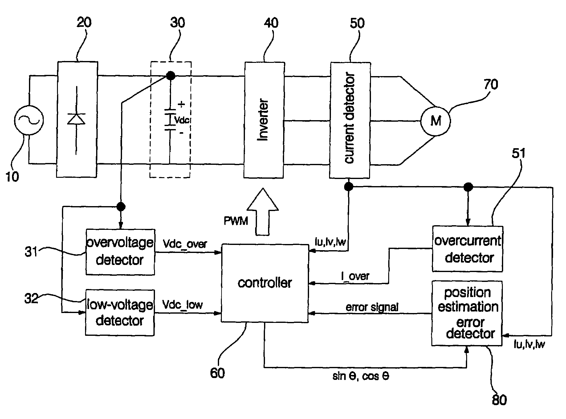
[0038]FIG. 2 is a block diagram illustrating a sensorless motor drive apparatus according to the present invention. Compared with the conventional sensorless motor drive apparatus of FIG. 1, the sensorless motor drive apparatus includes FIG. 2 further includes a position estimation error detector. Referring to FIG. 2, the sensorless motor drive apparatus includes a rectifier 20 for rectifying an AC voltage generated from an AC power source 10 to a DC voltage; a DC link 30 including a plurality of capacitors, for smoothin...


PUM


Abstract

A sensorless motor drive apparatus and a method for protecting and controlling the same. The sensorless motor drive apparatus includes a unit for determining the presence or absence of a position estimation error of a rotor contained in a motor using a current value applied to the motor and a position estimation angle of the rotor. Therefore, the sensorless motor drive apparatus determines the presence or absence of the position estimation error of the rotor without using a sensor, so that it reduces production costs, prevents the motor from generating a faulty operation, and prevents a compressor including the motor from being damaged.

Description

BACKGROUND OF THE INVENTION[0001]1. Field of the Invention[0002]The present invention relates to a sensorless motor drive apparatus and a method for protecting and controlling the same, and more particularly to a sensorless motor drive apparatus including a position estimation error detector so that it can determine whether an unexpected error occurs in estimating a position of a rotor of a motor with the sensorless method using a software method, and a method for protecting and controlling the sensorless motor drive apparatus.[0003]2. Description of the Related Art[0004]A conventional sensorless motor drive apparatus will hereinafter be described with reference to FIG. 1.[0005]FIG. 1 is a block diagram illustrating the conventional sensorless motor drive apparatus. Referring to FIG. 1, the conventional sensorless motor drive apparatus includes a rectifier 2 for rectifying an AC voltage generated from an AC power source 1 to a DC voltage; a DC link 3 including a plurality of capacit...

Claims


Application Information

Patent Timeline
Patent Type & Authority Patents(United States)
IPC IPC(8): H02P7/06H02P21/00H02P27/04H02P27/06H02P27/08
CPCH02P6/001H02P21/146H02P29/028H02P6/34H02P21/18H02P29/032H02H7/0833H02P6/06
Inventor WON, JUNE HEEOH, JAE YOONLEE, GIL SUCHEONG, DAL HOLEE, KYUNG HOON
Owner LG ELECTRONICS INC
Why Eureka
Try Eureka