Unlock instant, AI-driven research and patent intelligence for your innovation.

Hitless reconfiguration of a switching network

Active Publication Date: 2006-11-21
BAY MICROSYSTEMS INC
View PDF14 Cites 6 Cited by
  • Summary
  • Abstract
  • Description
  • Claims
  • Application Information

AI Technical Summary

Benefits of technology

[0013]In this manner, a switching network that ca

Problems solved by technology

Early fiber optic systems, however, were expensive because they used proprietary architectures, equipment line codes, multiplexing formats, etc., such that one fiber optic system could not be connected to another unless they were both from the same manufacturer.
A problem in the art is that current switching networks nodes generally have multiple stages to provide non-blocking paths for maximum throughput.
If a switching network is reconfigured immediately upon receipt of the automatic protection switching request, STS-N frames traversing the switching network are lost.
This time lag means that the communications takes a “hit”, because a portion of the communication signal is lost during the reconfiguration period.

Method used


Image

  • Hitless reconfiguration of a switching network
  • Hitless reconfiguration of a switching network
  • Hitless reconfiguration of a switching network

Examples


Embodiment Construction

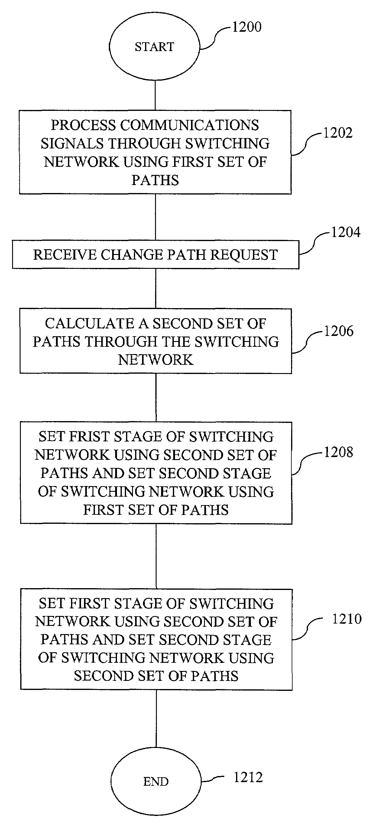
[0022]A switching network according to an exemplary embodiment of this invention may be constructed on a switching network platform in accordance with the one described in U.S. patent application Ser. No. 09 / 974,448, filed Oct. 10, 2001, and assigned to the assignee of this invention, which is incorporated herein in its entirety. The switching network described therein is a two-stage switch. The first stage comprises a space switch, and the second stage is a time and space switch. The first stage switches from an input into a first buffer, while the second stage switches from a second buffer (loaded in a previous frame by the first stage). The first stage then switches from the input to the second buffer, while the second stage switch from the first buffer to the output. Thus, data at the input is switched completely through the switching network in two frames.

[0023]A controller controls each stage separately. The controller designates the paths through each stage according to the s...


PUM


Abstract

A multi-stage switching network that can hitlessly reconfigure itself comprising a controller that controls each stage separately. The controller designates the paths through each stage according to the set of paths currently active. If the set of paths changes, the controller sends a new set of paths to the first stage while using the old set of paths for the second stage during a first frame. On the next frame, the controller causes both stages to use the new set of paths.

Description

CROSS-REFERENCE TO RELATED APPLICATION[0001]This patent application is related to U.S. patent application Ser. No. 09 / 974,448, filed Oct. 10, 2001, and assigned to the assignee of this invention.FIELD OF THE INVENTION[0002]This invention relates to the field of switching networks, and, more specifically, to a multi-stage switching network capable of switching communications signals according to a new set of paths through the switching network before all stages have finished switching previous communications signals according to a previous set of paths.BACKGROUND OF THE INVENTION[0003]Fiber optics transmission is the medium of choice for voice and data service provider networks. Currently, fiber optics provides the highest bandwidth per unit cost of any transmission medium. Early fiber optic systems, however, were expensive because they used proprietary architectures, equipment line codes, multiplexing formats, etc., such that one fiber optic system could not be connected to another ...

Claims


Application Information

Patent Timeline
IPC IPC(8): H04J3/02H04L12/28H04L12/56H04L12/66H04Q3/68
CPCH04Q3/68
Inventor ARBEL, YGALCAULK, ROBERT LOUISLOEFFLER-LEJEUNE, CHRISTOPH DOMINIQUE
Owner BAY MICROSYSTEMS INC