Phase frequency detector
a phase frequency and detector technology, applied in the direction of pulse automatic control, pulse technique, instruments, etc., can solve the problems of reducing power consumption, reducing power consumption, and reducing the operation speed of the pfd, so as to achieve fast phase lock, low noise characteristics, and low power consumption
- Summary
- Abstract
- Description
- Claims
- Application Information
AI Technical Summary
Benefits of technology
Problems solved by technology
Method used
Image
Examples
first embodiment
[0033]FIG. 6 is a circuit diagram for explaining a phase frequency detector according to the present invention.
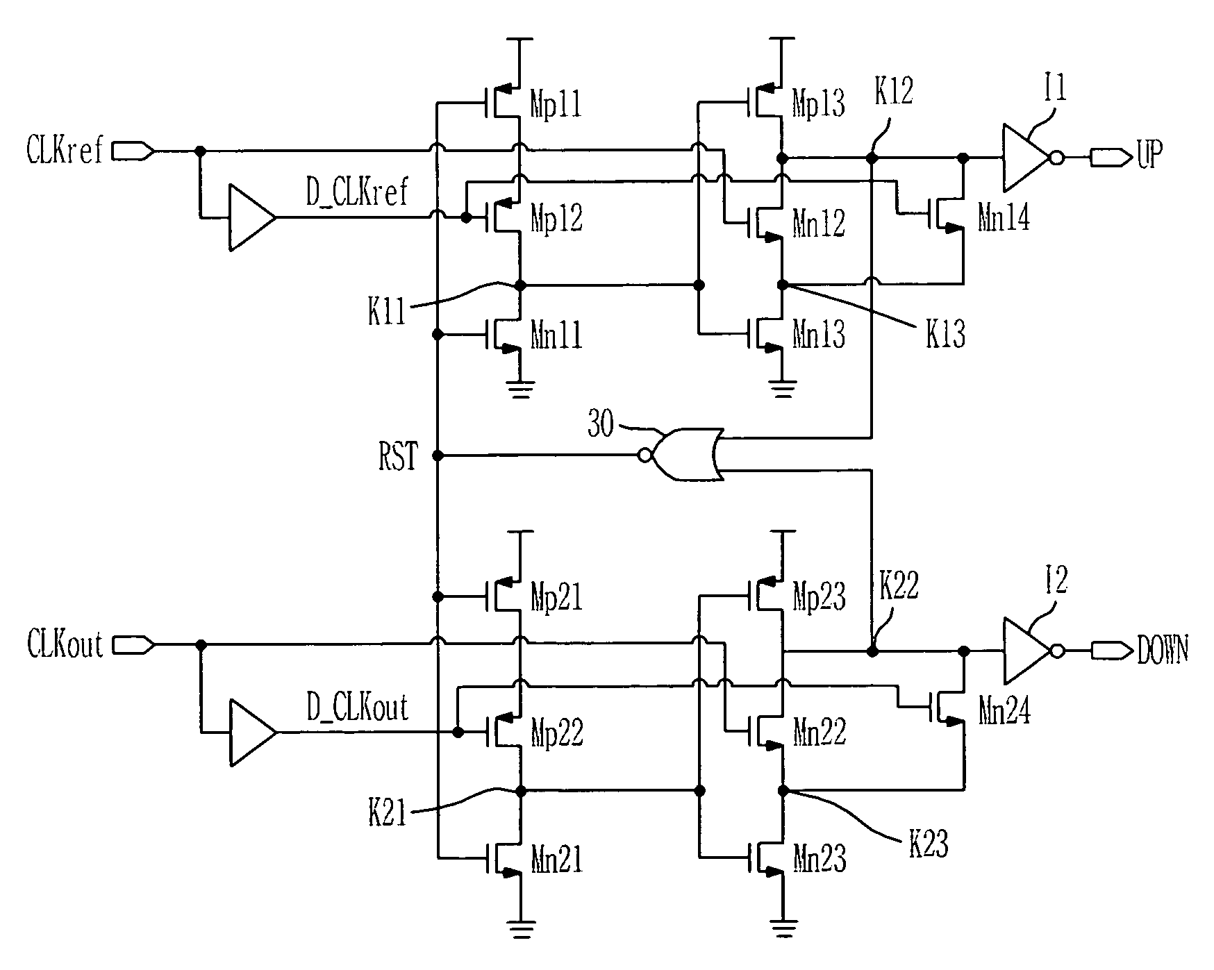
[0034]The phase frequency detector (PFD) of the present invention includes: an UP signal output unit 10 for receiving a reference clock CLKref and a predetermined time delayed reference clock D_CLKref; a DOWN signal output unit 20 for receiving an outer clock CLKout and a predetermined time delayed outer clock D_CLKout; and a logical gate for logically combining outputs of the UP signal output unit 10 and the DOWN signal output unit 20 to generate a reset signal RST.
[0035]The UP signal output unit 10 includes: a first stage operated according to the predetermined time delayed reference clock D_CLKref, delayed by delay means D1, and the reset signal RST; a second stage operated according to the reference clock CLKref and an output of the first stage; and an inverter I1 for inverting an output of the second stage.
[0036]The first stage includes transistors Mp11 and Mp12 connec...
second embodiment
[0052]FIG. 8 is a circuit diagram for explaining a phase frequency detector according to the present invention, where transistors Mn14 and Mn24 are added to the phase frequency detector of FIG. 6.
[0053]The transistor Mn14 connected between the output node K12 and a node K13 receives the delayed reference clock D_CLKref through a gate, and the transistor Mn24 connected between the output node K22 and a node K23 receives the delayed outer clock D_CLKout through a gate.
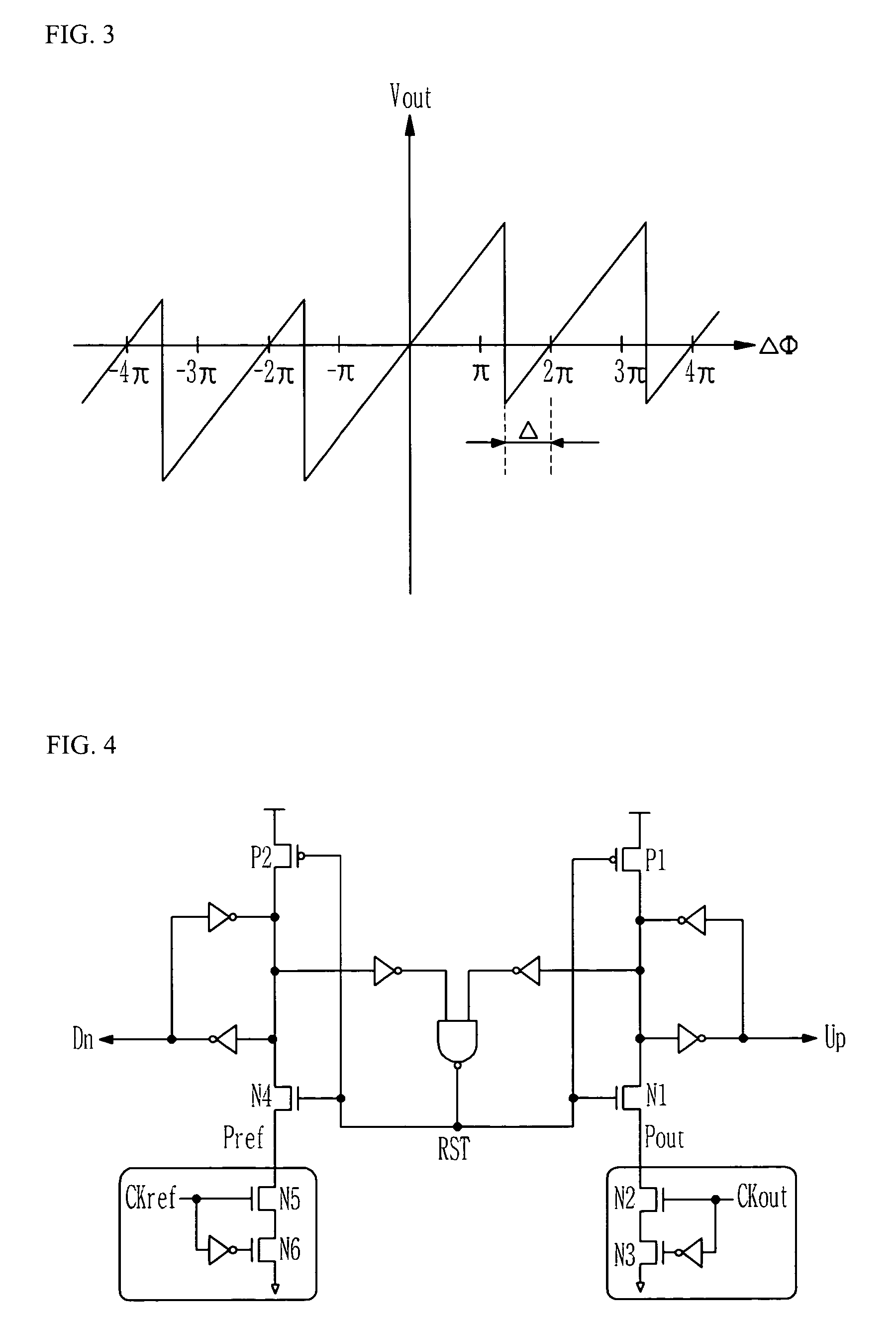
[0054]The PFD according to the present embodiment has the same operation characteristic as that of FIG. 5, and the cutoff frequency becomes td5*fclk*2π<π, which is different from that for the PFD of FIG. 6. Therefore, the cutoff frequency is twice higher than that for the PFD of FIG. 6. This is the same cutoff frequency as that for the conventional PFD arranged as shown in FIG. 4.
[0055]The PFD according to the present invention has almost the same power consumption and noise characteristic as the PFD of FIG. 6, so that i...
PUM
 Abstract
Description
Claims
Application Information
 - R&D
- Intellectual Property
- Life Sciences
- Materials
- Tech Scout
- Unparalleled Data Quality
- Higher Quality Content
- 60% Fewer Hallucinations
Browse by: Latest US Patents, China's latest patents, Technical Efficacy Thesaurus, Application Domain, Technology Topic, Popular Technical Reports.
© 2025 PatSnap. All rights reserved.Legal|Privacy policy|Modern Slavery Act Transparency Statement|Sitemap|About US| Contact US: help@patsnap.com


