Source synchronous bus repeater

a synchronous bus and source technology, applied in the field of digital communication, can solve problems such as clock skew, inherent phase delay that may accumulate, and inability to adapt to the direction of pulse technique, pulse transformer,

a synchronous bus and source technology, applied in the field of digital communication, can solve problems such as clock skew, inherent phase delay that may accumulate, and inability to adapt to the direction of pulse technique, pulse transformer,

US7139308B2Active Publication Date: 2006-11-21ORACLE INT CORP

Image

  • Source synchronous bus repeater
  • Source synchronous bus repeater
  • Source synchronous bus repeater

Examples


Embodiment Construction

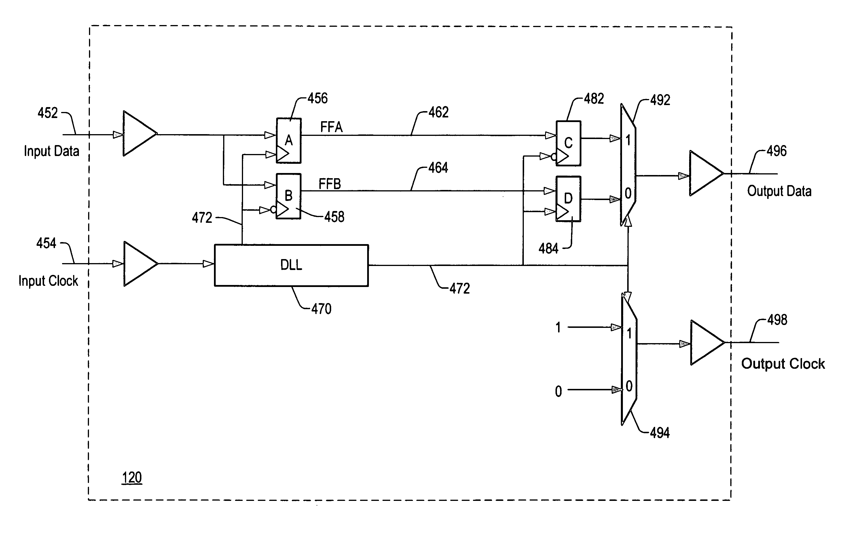
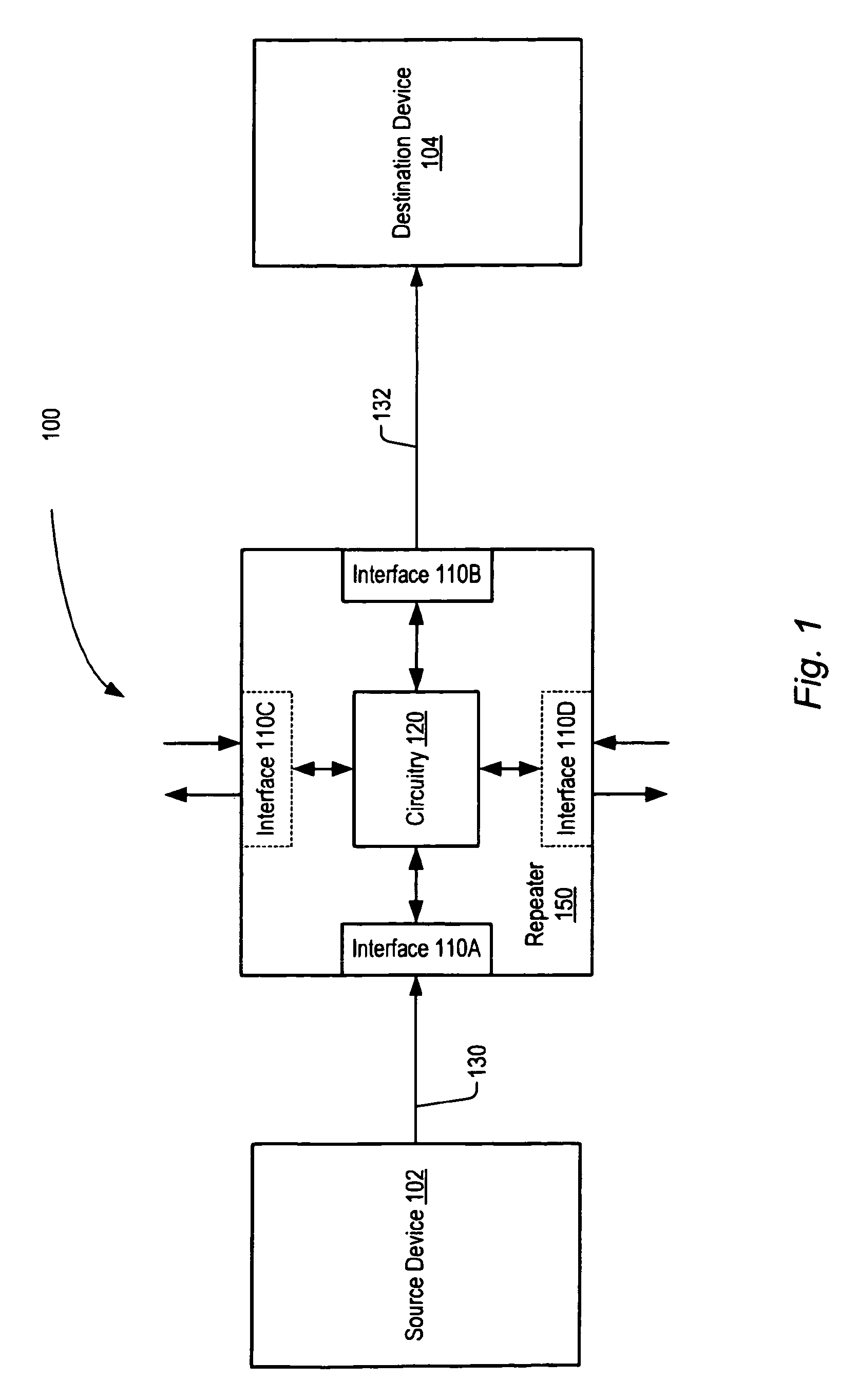
[0020]FIG. 1 illustrates one embodiment of a source synchronous system 100 configured to transmit signals. In the example shown, a source device 102 is configured to convey signals to a destination device 104. Also shown in FIG. 1 is a retimer chip 150 coupled between source device 102 and destination device 104. Retimer chip 150 includes input port 110A which is coupled to receive source synchronous signals from source device 102 via bus 130. Retimer chip 150 also includes output port 110B which is coupled to convey source synchronous signals to destination device 104 via bus 132. Also included in retimer chip 150 is circuitry 120, and optional additional ports 110C and 110D.

[0021]In one embodiment, source device 102 and destination device 104 may be physically separated by such a distance that signal degradation precludes efficient signal transmission directly from source device 102 to destination device 104. Therefore, rather than directly coupling source device 102 to destinatio...


PUM


Abstract

A device configured to recover and repeat source synchronous data. In one embodiment, the device is configured to receive source synchronous data via a first interface, recover the received data utilizing a corresponding received source synchronous clock signal, and transmit the recovered data and a corresponding clock signal in a source synchronous manner. In one embodiment, the device is configured to operate as a repeater without benefit of an internal clock signal. In addition, the device may be configured to remove data jitter and renew or restore amplitude to attenuated signals prior to retransmission.

Description

BACKGROUND OF THE INVENTION[0001]1. Field of the Invention[0002]This invention is related to the field of digital communications and, more particularly, to the transmission of digital signals.[0003]2. Description of the Related Art[0004]The design of advanced digital communication systems requires careful attention to the reliable transmission and receipt of signals in order to ensure proper functioning. One popular design methodology is that of synchronous design. Generally speaking, synchronous designs utilize a central clock which is distributed to various parts of the design. While utilizing a synchronous approach may simplify certain aspects of the design process, this approach is not without its problems. One such problem is that of clock skew. Because a central clock signal may be distributed to various parts of a system via board traces, backplanes, interconnects, and the like, clock skew may exceed that which can be tolerated by registers and other elements. Consequently, d...

Claims


Application Information

Patent Timeline
21 Nov 2006
Publication
US7139308B2
IPC
H04L25/60; H04L7/00
CPC
H04L7/0008; H04L7/0045
Inventors
DOBLAR, DREW G.; JONG, JYH-MING