Fiber optic gasket and enclosure

a fiber optic and gasket technology, applied in the field of fiber optic gaskets and enclosures, can solve the problems of computer systems, electromagnetic effects that cannot be minimized in optical implementations, and achieve the effect of reducing disadvantages and problems, reducing the amount of electromagnetic energy, and eliminating or greatly reducing disadvantages

Active Publication Date: 2006-11-21
TELLABS OPERATIONS
View PDF5 Cites 76 Cited by
  • Summary
  • Abstract
  • Description
  • Claims
  • Application Information

AI Technical Summary

Benefits of technology

[0004]From the foregoing, it may be appreciated by those skilled in the art that a need has arisen for an electrically conductive enclosure that minimizes an amount of electromagnetic energy that can enter or exit when employing fiber optic links. In accordance with the present invention, a fiber optic gasket and enclosure are provided that substantially eliminate or greatly reduce disadvantages and problems associated with conventional fiber optic systems.

Problems solved by technology

Due to this misperception, most fiber optic implementations do not minimize the effect of electromagnetic interference.
Electro-magnetic interference may enter and leave a computer system in various ways.
In particular, electro-magnetic interference may enter or leave a computer system enclosure through an electrical aperture associated with a fiber optic cable connector.

Method used


Image

  • Fiber optic gasket and enclosure
  • Fiber optic gasket and enclosure
  • Fiber optic gasket and enclosure

Examples


Embodiment Construction

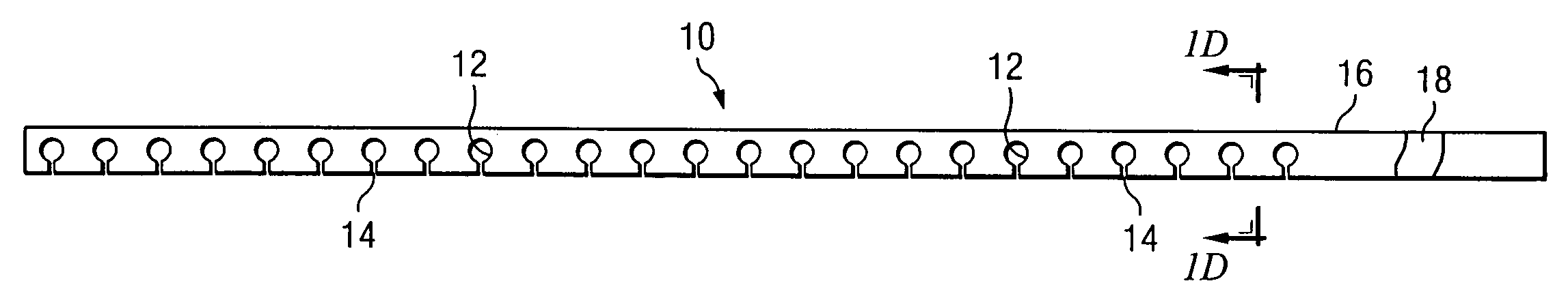
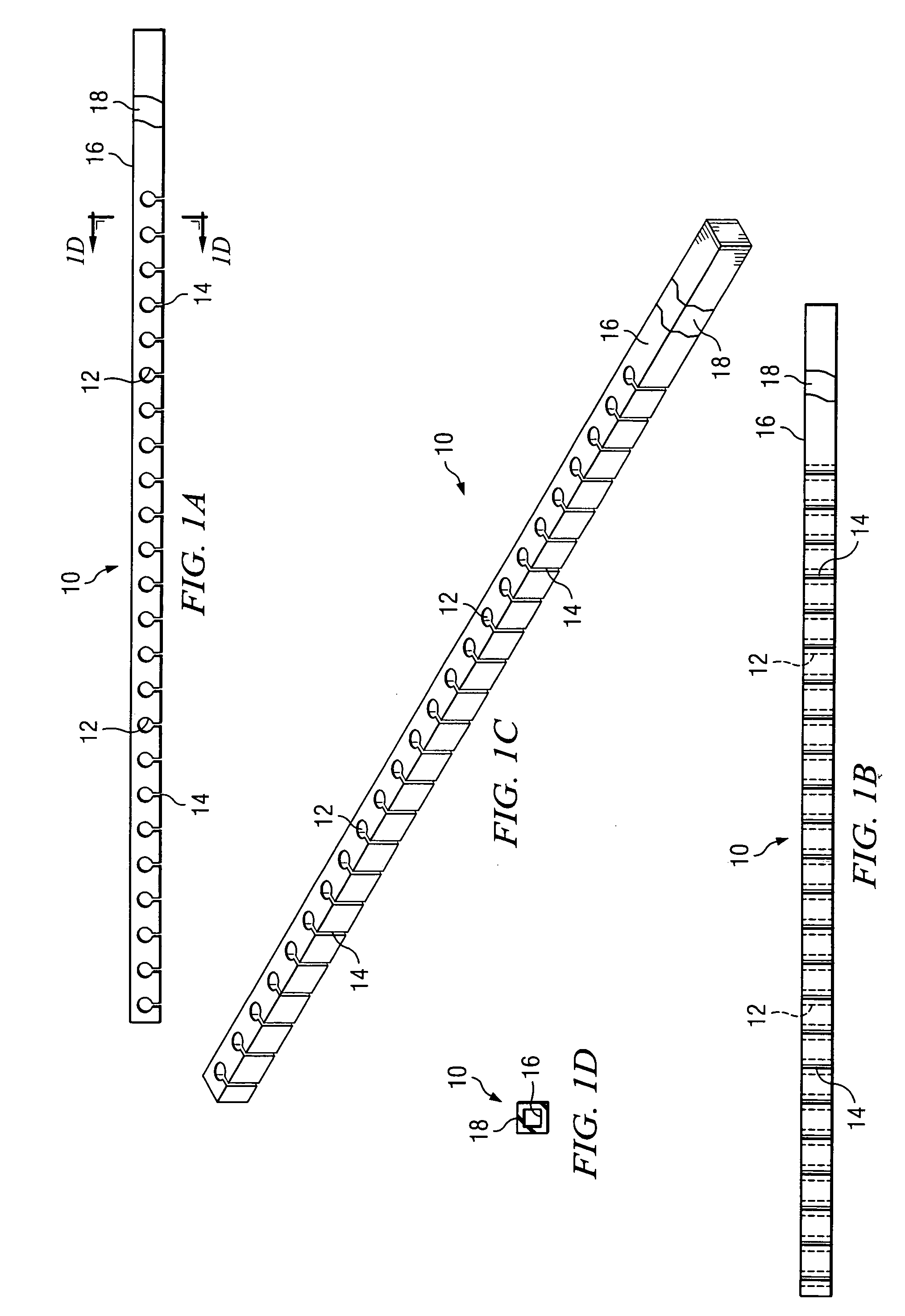
[0012]FIGS. 1A–1D are diagrams of a fiber optic gasket 10 according to an example embodiment of the present invention. Fiber optic gasket 10 includes one or more apertures 12. At each aperture 12, fiber optic gasket 10 may include a slit 14 that extends from aperture 12 to one side of fiber optic gasket 10. Alternatively, in another example embodiment, slit 14 is adjacent to aperture 12 but does not extend to one side of fiber optic gasket 10. Fiber optic gasket 10 includes structural material 16 that defines the shape and structural properties for fiber optic gasket 10. Structural material 16 may be made from any non-conductive or conductive matter as desired. For example, structural material 16 may be made from flexible foam. Surrounding structural material 16 is a layer of conductive material 18. Conductive material 18 may be applied to structural material 16 before or after apertures 12 and slits 14 are formed in fiber optic gasket 10. Alternatively, conductive material 18 may b...


PUM


Abstract

A fiber optic gasket includes one or more apertures to individually retain optical fibers from one or more fiber optic cards positioned within an enclosure. A slit within the fiber optic gasket associated with each aperture facilitates placement of an optical fiber within an aperture. The fiber optic gasket includes a layer of conductive material for electromagnetic interference protection. When installed in the enclosure, the fiber optic gasket comes in contact with a door that is removably connected to the enclosure. An electro-magnetic interference shield is provided at the interface between the door and the fiber optic gasket. Optical fibers can extend out of the enclosure without causing harmful electromagnetic energy from leaving or entering the enclosure.

Description

TECHNICAL FIELD OF THE INVENTION[0001]The present invention relates in general to telecommunications equipment and more particularly to a fiber optic gasket and enclosure.BACKGROUND OF THE INVENTION[0002]Systems for transmitting large blocks of data in short intervals of time or transmitting high speed data over relatively long distances use fiber optic links. A common misperception associated with the use of fiber optic links is that fiber optic links eliminate all problems related to electromagnetic interference. Due to this misperception, most fiber optic implementations do not minimize the effect of electromagnetic interference.[0003]Electro-magnetic interference may enter and leave a computer system in various ways. In particular, electro-magnetic interference may enter or leave a computer system enclosure through an electrical aperture associated with a fiber optic cable connector. The electrical aperture occurs between the fiber optic connector and the computer system enclosu...

Claims


Application Information

Patent Timeline
Patent Type & Authority Patents(United States)
IPC IPC(8): G02B6/00H01R33/945
CPCG02B6/4471G02B6/4452
Inventor RICHTMAN, MARK P.
Owner TELLABS OPERATIONS
Why Eureka
Try Eureka