Wavelength division multiplex transmission system

Inactive Publication Date: 2006-11-21
OKI ELECTRIC IND CO LTD
View PDF6 Cites 6 Cited by
  • Summary
  • Abstract
  • Description
  • Claims
  • Application Information

AI Technical Summary

Benefits of technology

[0016]This invention was devised in consideration of the above problems, and provides a wavelength division multiplex transmission system with satisfactory transmission characteristics, and which has enhanced functions for defect avoidance.

Problems solved by technology

However, route selection methods in conventional WDM systems have been route selection methods the selection criteria of which do not reflect important factors influencing transmission quality, such as the number of repeaters or traffic conditions.
Hence in this case also, the selected route is not necessarily optimal with respect to the transmission characteristics of optical signals.
Further, whichever route selection method is used, if the same route is selected for a number of data sets, a large amount of data is concentrated in a given route to result in congestion, and problems such as circuit breaks may occur.
In addition, if a malfunction occurs in an NE on the transmission route, another route is used in place of that transmission route, and consequently the tendency toward congestion in the WDM transmission network is intensified, giving rise to the problem that the probability of circuit breaks is increased.
As explained above, conventional route selection methods are not suitable from the standpoint of securing transmission quality.
In particular, when a defect occurs and routes are reallocated, in extreme cases, large amounts of empty band capacity may occur in a certain route.
However, even in such cases this route may not be selected by the above-described conventional route selection methods, and consequently data may be concentrated in one particular route or a plurality of routes.
That is, there is the possibility that an empty route may not be selected, because the transmission distance is long or the number of hops is large.
Further, in conventional route selection methods in which data is concentrated in a given route, if a currently utilized route is cut off, route switching is necessary for a large amount of data at once, and this may be the cause of a higher probability of congestion.
Even in cases in which the optical transmission device transmitting WDM signals and the optical receiving device receiving WDM signals comprise an operation system and standby system, the same route is adopted by the operation system and by the standby system, so that the above-described problem with route selection methods cannot be resolved.
In this case, only defects within the operation system of the optical transmission device and optical receiving device can be accommodated.

Method used


Image

  • Wavelength division multiplex transmission system
  • Wavelength division multiplex transmission system
  • Wavelength division multiplex transmission system

Examples


first embodiment

[0046](A) First Embodiment

[0047]With reference to the drawings, a detailed description of a first embodiment of the wavelength division multiplex transmission system according to the present invention will be herehinafter given.

[0048](A-1) Configuration of First Embodiment

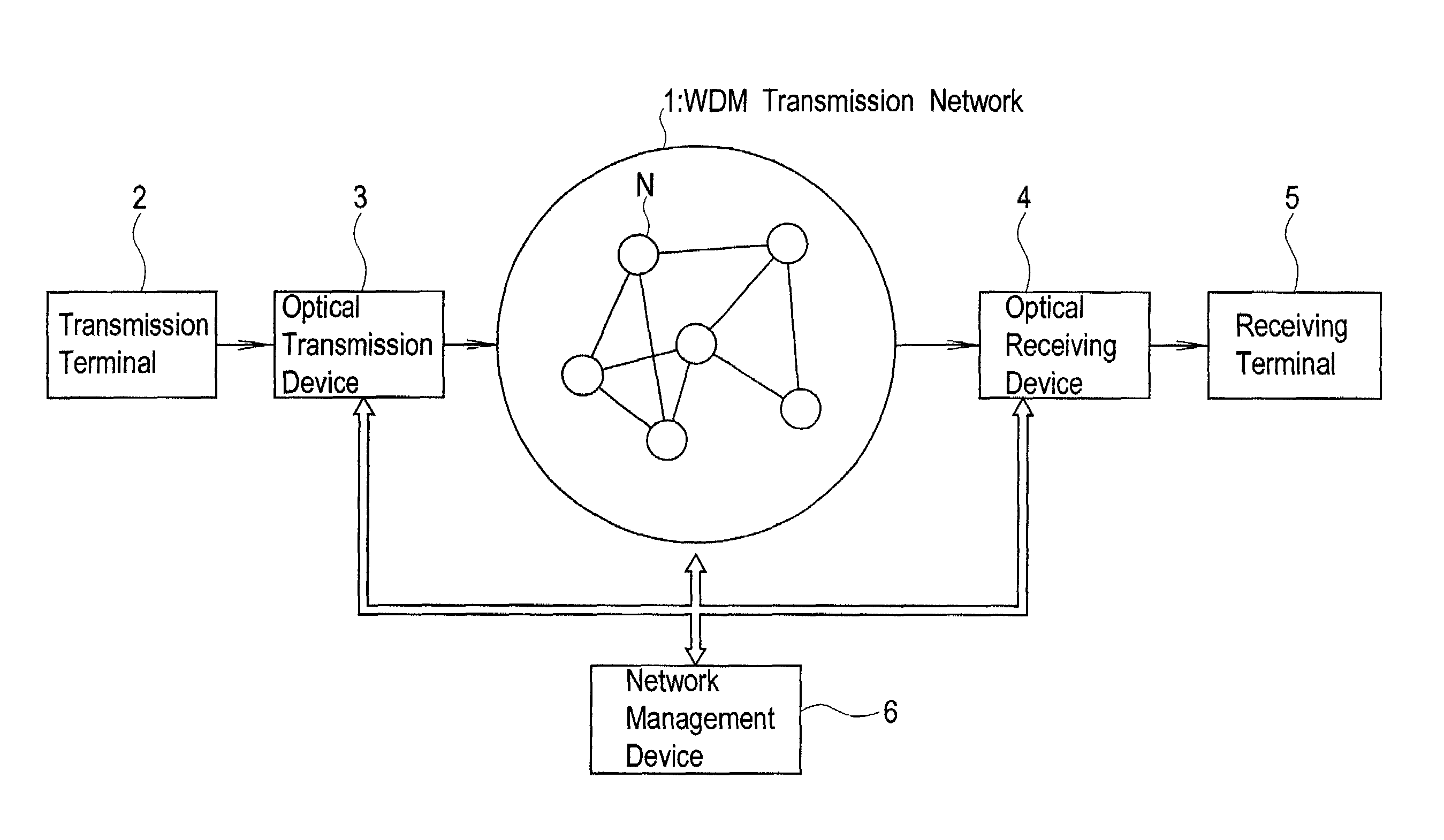
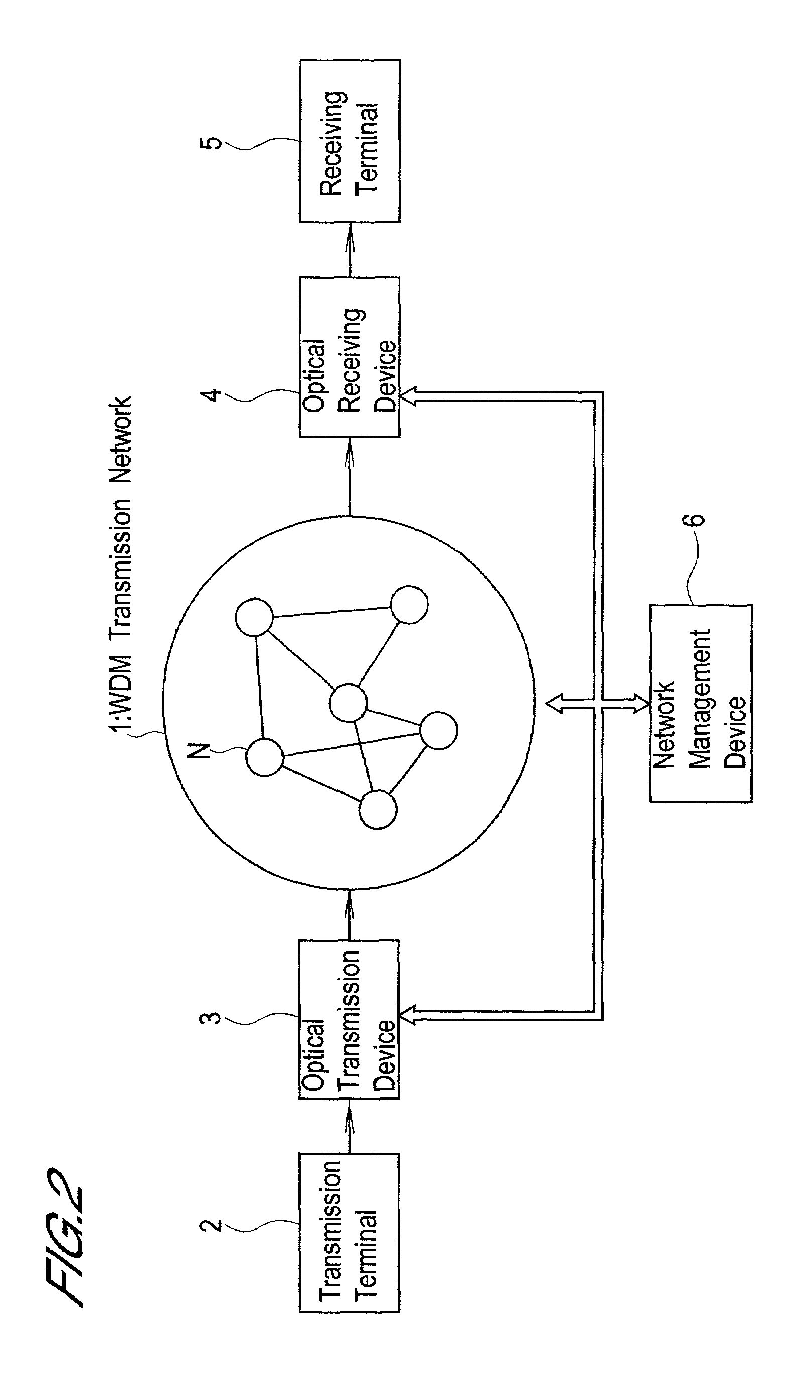
[0049]Referring to FIG. 2, the wavelength division multiplex transmission system of the first embodiment has a WDM transmission network 1; an optical transmission device 3 which converts transmission signals (electrical signals) from a transmission terminal 2 into optical signals (WDM signals) and transmits the optical signals over the WDM transmission network; an optical receiving device 4 which changes WDM signals received from the WDM transmission network 1 into electrical signals and applies the electrical signals to the receiving terminal 5; and a network management device 6 which is responsible for management functions for the WDM transmission network 1, optical transmission device 3, optical receiving device...

second embodiment

[0175](B) Second Embodiment

[0176]Next, a second embodiment of the wavelength division multiplex transmission system of this invention is explained in detail, referring to the drawings.

[0177](B-1) Configuration of the Second Embodiment

[0178]FIG. 19 is a block diagram showing the configuration of principal components of the optical transmission device 3X of the second embodiment; parts which are the same or corresponding in FIG. 4 for the first embodiment are assigned corresponding symbols.

[0179]In addition to the configuration of the first embodiment, the optical transmission device 3X of this second embodiment is provided with an auxiliary optical channel card 13-S. The auxiliary optical channel card 13-S functions whenever a defect occurs in one of the optical channel cards 13-1 to 13-n or in one of the optical receiving cards 32-1 to 32-n of the opposing optical receiving device 4X (see FIG. 20). A wavelength component λs, different from the wavelength components λ1 to λn of the o...

third embodiment

[0197](C) Third Embodiment

[0198]Next, a third embodiment of the wavelength division multiplex transmission system of this invention is explained in detail, referring to the drawings.

[0199](C-1) Configuration of the Third Embodiment

[0200]FIG. 22 is a block diagram showing the configuration of principal components of the optical transmission device 3Y of the third embodiment; parts which are the same or corresponding in FIG. 4 for the first embodiment are assigned corresponding symbols.

[0201]In addition to the configuration of the first embodiment, the optical transmission device 3Y of this third embodiment is provided with an auxiliary optical channel card 13-t and optical switch (optical SW) 19.

[0202]The auxiliary optical channel card 13-t functions when a defect occurs in one of the optical channel cards 13-1 to 13-n. This auxiliary optical channel card 13-t of the third embodiment can capture, under instructions from outside, wavelengths within the range of the wavelength componen...


PUM


Abstract

There is provided a wavelength division multiplex transmission system with satisfactory transmission characteristics and extensive functions for avoidance of defects. Transmission signals to be transmitted by an optical transmission device are distributed among a plurality of wavelength components, converted into WDM signals, and sent to a WDM transmission network, and WDM signals from the WDM transmission network are restored to the transmission signals by an optical receiving device. This system includes a wavelength component-specific route setting device which sets routes for transmission on the WDM transmission network for each wavelength component.

Description

BACKGROUND OF THE INVENTION[0001]1. Field of the Invention[0002]This invention concerns a wavelength division multiplex transmission system, and in particular routing control and defect processing.[0003]2. Description of Related Art[0004]Current trends in technology for increasing the capacity of optical communication systems can be broadly divided into time-division multiplex (TDM) methods, and wavelength-division multiplex (WDM) methods.[0005]In WDM methods, signals are modulated at, for example, 10 Gbps per channel. In each channel, modulated signals at different wavelengths are superposed by a four-channel WDM optical coupler (wavelength division multiplexer), and by transmitting the resulting signal over a single optical fiber, transmission at 40 Gbps can be achieved. This WDM method has been described as being superior to the TDM method with respect to such areas as ease of upgrading, power division costs, security, and service flexibility.[0006]In conventional systems using t...

Claims


Application Information

Patent Timeline
IPC IPC(8): H04J14/00H04B10/03H04B10/032H04B10/038H04B10/079H04B10/27H04B10/275H04J3/14H04J14/02
CPCH04J3/14H04J14/0227H04J14/029H04J14/0295H04J14/0297H04J14/0246H04J14/0284
Inventor SUZUKI, MIKIYAISHIMURA, KATSUHIRO
Owner OKI ELECTRIC IND CO LTD
Why Eureka
Try Eureka