Error-correcting multi-stage code generator and decoder for communication systems having single transmitters or multiple transmitters

a multi-stage code generator and communication system technology, applied in coding, instruments, amplitude demodulation, etc., can solve the problems of undesirable inefficiencies of the transmission system, many useless duplicate segments, and many useless duplicate segments received by the receiver, so as to reduce the computational cost of encoding data for transmission over a channel and reduce the computational cost of decoding such data

Active Publication Date: 2006-11-21
QUALCOMM INC
View PDF3 Cites 64 Cited by
  • Summary
  • Abstract
  • Description
  • Claims
  • Application Information

AI Technical Summary

Benefits of technology

[0019]In a decoder according to embodiments of the present invention, the decoder can correctly decode the input symbols even when it only receives an arbitrary portion of the transmitted output symbols, and even if a substantial number of the received output symbols are in error. The input data can be decoded from any set of output symbol bits whose cumulative information is equal to, or slightly greater than, the number of input symbol bits comprising the file.
[0021]According to yet another embodiment of the invention, a computer data signal embodied in a carrier wave is provided. The computer data signal is usable for error corrections and includes a plurality of output symbols, wherein the plurality of output symbols represents symbols generated from a combined set of symbols including an ordered set of input symbols and the redundant symbols, wherein the redundant symbols are generated from the input symbols, wherein the number of possible output symbols is much larger than the number of symbols in the combined set of symbols, wherein at least one output symbol is generated from more than one symbol in the combined set of symbols and from less than all of the symbols in the combined set of symbols, and such that a receiver of the data signal can regenerate the ordered set of input symbols to a desired degree of accuracy from any predetermined number of the output symbols.
[0022]Numerous benefits are achieved by way of the present invention. For example, in a specific embodiment, the computational expense of encoding data for transmission over a channel is reduced. In another specific embodiment, the computational expense of decoding such data is reduced. Depending upon the embodiment, one or more of these benefits may be achieved. These and other benefits are provided in more detail throughout the present specification and more particularly below.

Problems solved by technology

Lost data (erasures) are often easier to deal with than corrupted data (errors) because the recipient cannot always tell when corrupted data is data received in error.
In a typical multiple sender system sending data to a receiver, if the senders do not coordinate which data they will transmit and when, but instead just send segments of the file, it is likely that a receiver will receive many useless duplicate segments.
If the sender just sends segments of the original file and repeats and some segments are lost, it is likely that a receiver will receive many useless duplicate segments before receiving one copy of each segment in the file.
Often this leads to undesirable inefficiencies of the transmission system.
One problem with some FEC codes is that they require excessive computing power or memory to operate.
Another problem is that the number of output symbols must often be determined in advance of the coding process.
This can lead to inefficiencies if the error rate of the symbols is overestimated and can lead to failure if the error rate is underestimated.
In such a case, this probing has to be repeated quite often, since the actual noise is a moving target due to rapid and transient changes in the quality of the communications channel.
As discussed above, one problem with many error-correcting codes is that they require excessive computing power or memory to operate.
This leads to inefficiencies if the error rate of symbols is overestimated, and can lead to failure if the error rate is underestimated.
This limitation is generally acceptable for many communications problems, so long as the rate of the code is selected properly, but this requires an advance guess at the error rate of the symbol reception of the channel.
Another disadvantage of LDPC codes is that they require the encoder and decoder to agree in some manner on a graph structure.
LDPC codes require a pre-processing stage at the decoder where this graph is constructed, a process that may slow the decoding substantially.
These graphs may be of significant size and may require a significant amount of memory for their storage at both the sender and the recipient.
Furthermore, values of N greater than a small multiple of K, such as 3 or 4 times K, are not practical.
Even though the output symbols from different transmitters may be corrupted in different ways, the total amount of information they convey to the system is not the sum of their respective amounts of information.

Method used


Image

  • Error-correcting multi-stage code generator and decoder for communication systems having single transmitters or multiple transmitters
  • Error-correcting multi-stage code generator and decoder for communication systems having single transmitters or multiple transmitters
  • Error-correcting multi-stage code generator and decoder for communication systems having single transmitters or multiple transmitters

Examples


Embodiment Construction

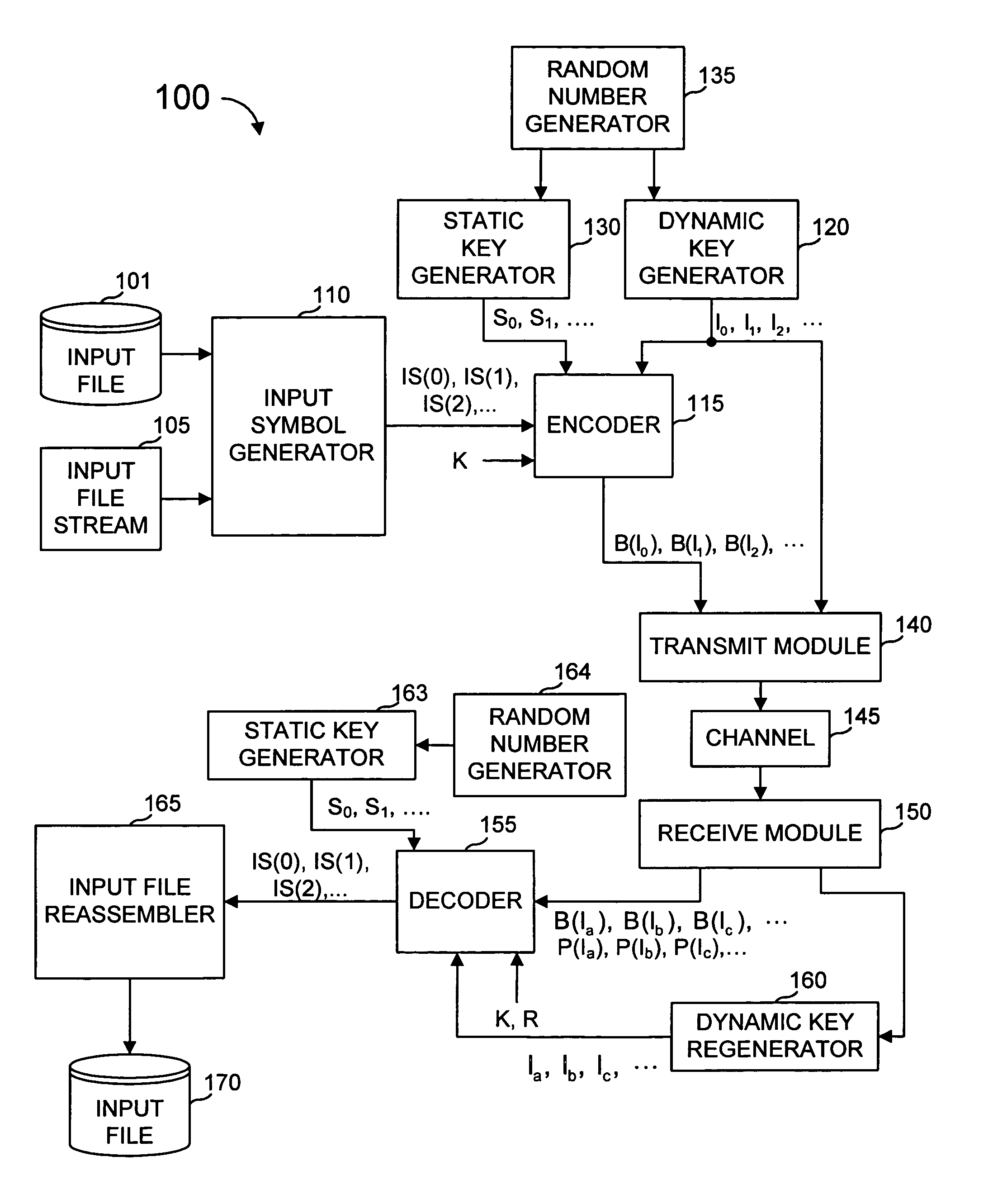
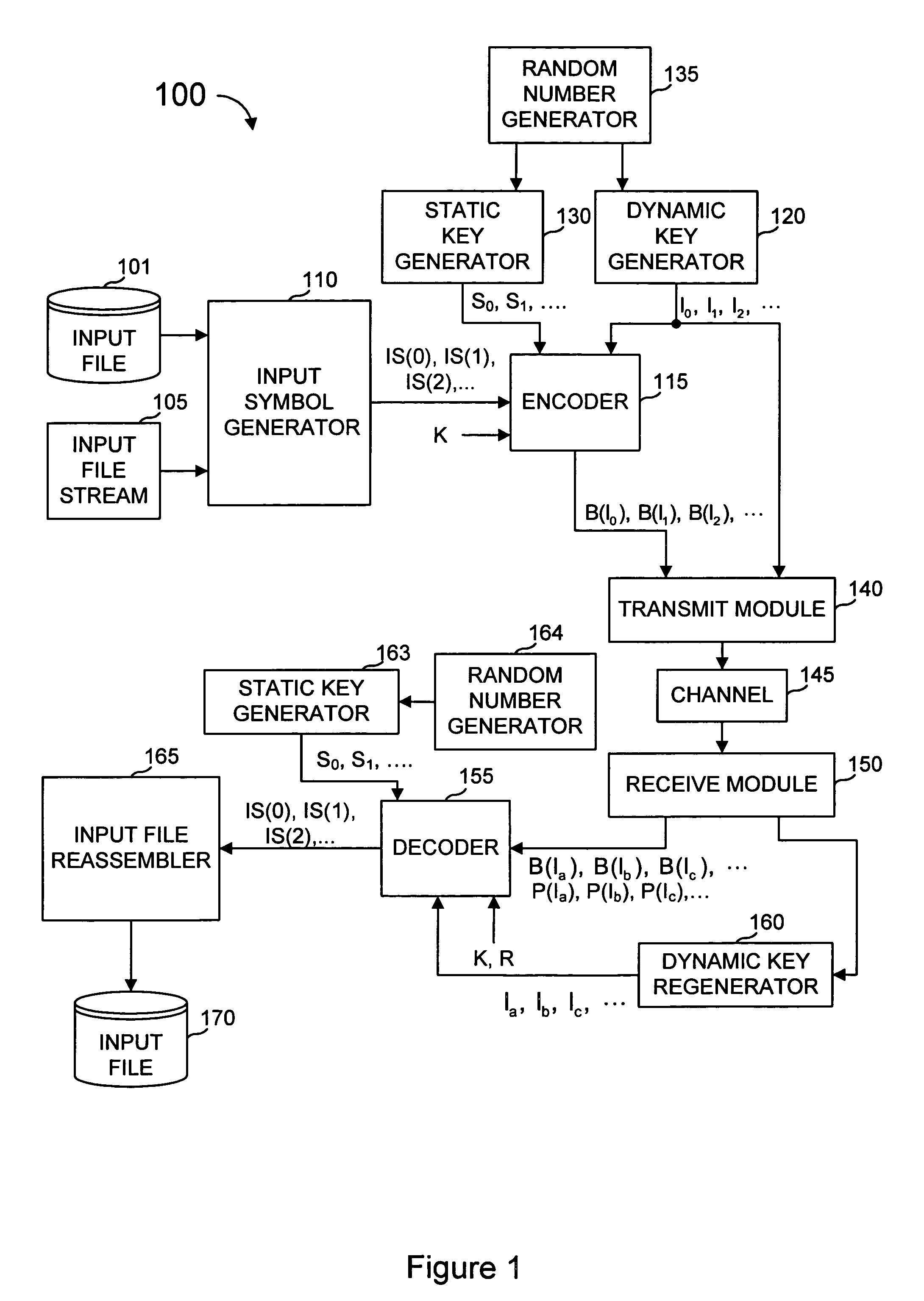
[0041]In the specific embodiments described herein, a coding scheme denoted as “error-correcting multi-stage coding” (“EC-MS”) is described, preceded by an explanation of the meaning and scope of various terms used in this description. Luby I and Shokrollahi I provide teachings of systems and methods that can be employed in certain embodiments according to the present invention. It is to be understood, however, that these systems and methods are not required of the present invention, and many other variations, modifications, or alternatives can also be used. Some variations of EC-MS and multi-stage coding might be used in products marketed as Digital Fountain Raptor code systems.

[0042]With EC-MS coding, output symbols are generated by the sender from the input file as needed. Each output symbol can be generated without regard to how other output symbols are generated. At any point in time, the sender can stop generating output symbols and there need not be any constraint as to when ...


PUM


Abstract

A communications system includes an encoder that produces a plurality of redundant symbols. For a given key, an output symbol is generated from a combined set of symbols including the input symbols and the redundant symbols. The output symbols are generally independent of each other, and an effectively unbounded number of output symbols can be generated, if needed. Received output symbols can provide probabilistic information for error correction. A decoder calculates check symbols from the output symbols received. For each received output symbol, the decoder updates a running total of estimated information content and, in one or more rounds, generates a probability distribution for each input symbol over all or some of possible values. This process may be repeated until, for all of the input symbols, one of the many possible values is much more probable than others, or the process may be repeated a predetermined number of rounds, or other criteria is met.

Description

CROSS-REFERENCES TO RELATED APPLICATIONS[0001]This application claims priority from co-pending U.S. Provisional Patent Application No. 60 / 509,355 filed Oct. 6, 2003 entitled “Error-Correcting Raptor Codes” which is hereby incorporated by reference, as if set forth in full in this document, for all purposes.[0002]The present disclosure is related to the following commonly assigned applications / patents: U.S. Pat. No. 6,307,487 to Michael G. Luby entitled “Information Additive Code Generator and Decoder for Communication Systems” (hereinafter “Luby I”), U.S. Pat. No. 7,068,729, to M. Amin Shokrollahi et al [U.S. patent application Ser. No. 10 / 032,156, filed Dec. 21, 2001] entitled “Multi-Stage Code Generator and Decoder for Communication Systems” (hereinafter “Shokrollahi I”), and U.S. Pat. No. 6,909,383, to M. Amin Shokrollahi et al, entitled “Systematic Encoding and Decoding of Chain Reaction Codes” (hereinafter “SED-CRC”). The respective disclosures of these applications / patents are...

Claims


Application Information

Patent Timeline
Patent Type & Authority Patents(United States)
IPC IPC(8): H03M13/00G06F11/00G06F11/30G08C25/00H03D1/00H03MH03M13/37H04L1/00H04L27/06
CPCH03M13/3761H03M13/00G06F11/00
Inventor SHOKROLLAHI, M. AMIN
Owner QUALCOMM INC
Why Eureka
Try Eureka