Cell safety valve and cell having same

a cell safety valve and cell technology, applied in the field of cell safety valves, can solve the problems of difficult control of the operating pressure large amount of gas produced in the cell, and difficulty in the operation of the safety valve, so as to achieve the effect of enlarging the opening area of the safety valve and quickly releasing the gas generated

Inactive Publication Date: 2006-11-28
SANYO ELECTRIC CO LTD
View PDF19 Cites 21 Cited by
  • Summary
  • Abstract
  • Description
  • Claims
  • Application Information

AI Technical Summary

Benefits of technology

[0020]In addition, the intersection point of the break aiding groove and the break groove serves as a point of starting the breaking, and consequently the whole of the break groove breaks, thus enlarging the opening area of the safety valve. Accordingly, it is made possible to quickly release a gas generated abnormally inside the cell.
[0021]When dropping impact is applied, a more stress is applied on the break aiding gro

Problems solved by technology

When such a non-aqueous electrolyte cell is mishandled, e.g., put in fire, charged or discharged under abnormal conditions, a great amount of gas may be produced in the cell.
In such a configuration of the safety valve, when an internal cell pressure rises, deformation volume of the periphery of the safety valve is so small that it is difficult for the safety valve to operate when the cell has a small internal pressure, and it is also difficult to control the operating pressure of the safety valve.
In addition, the breaking of the safety valve is too small in area to release a gas

Method used


Image

  • Cell safety valve and cell having same
  • Cell safety valve and cell having same
  • Cell safety valve and cell having same

Examples


example 1

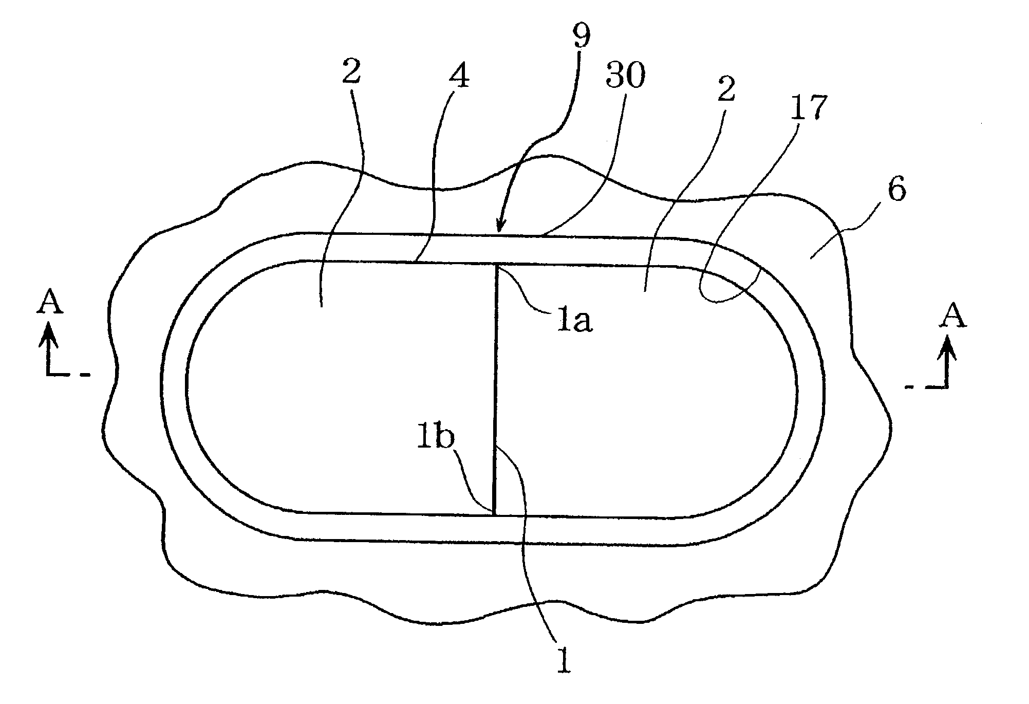
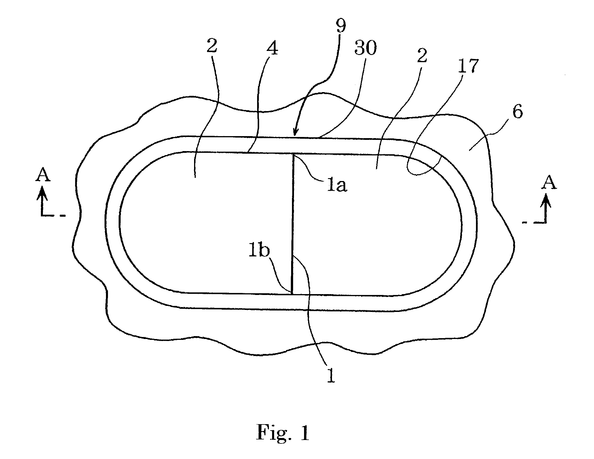
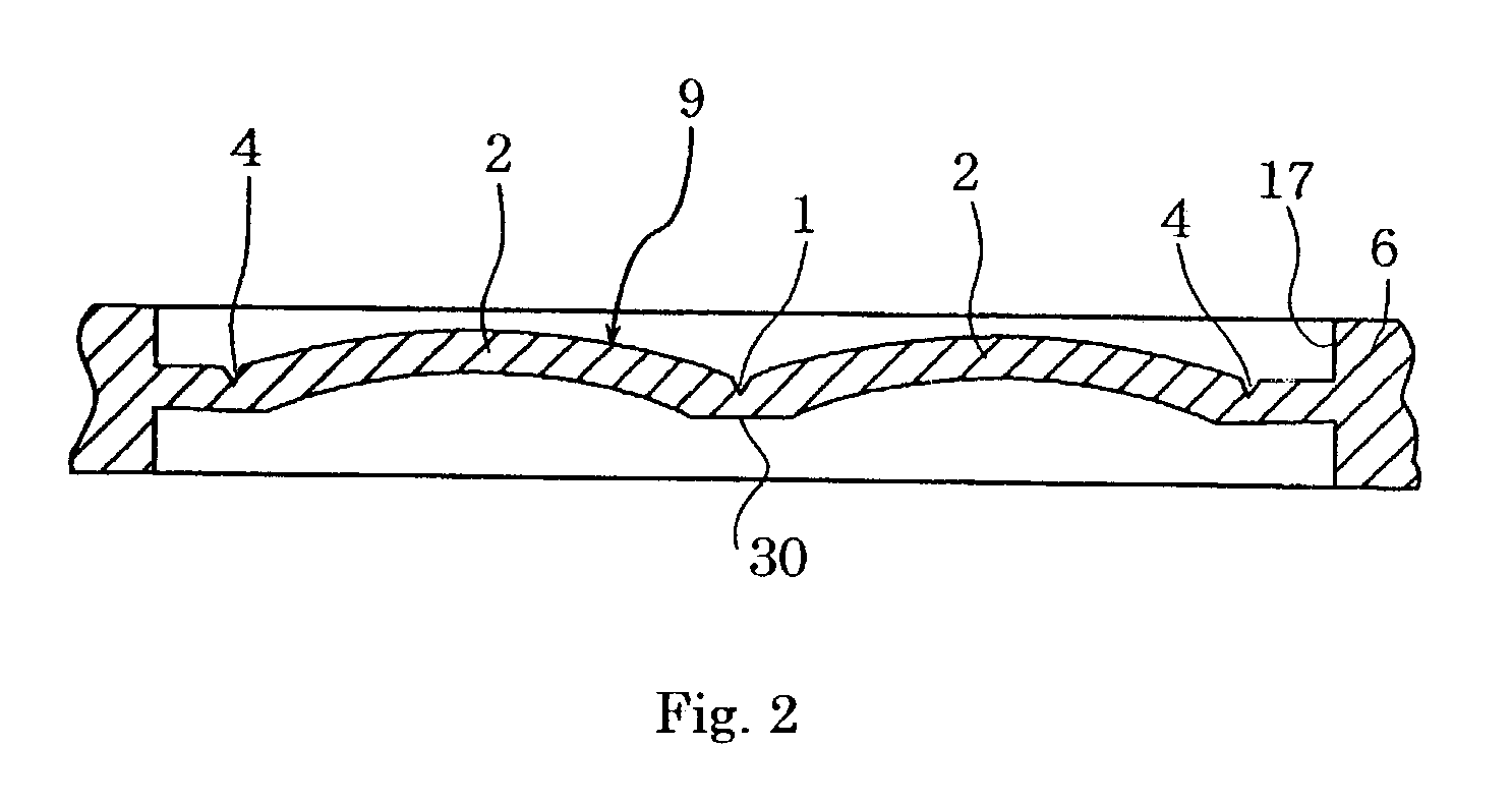
[0083]An example of the present invention will be described below based on FIGS. 1–13.

[0084]FIG. 1 is a plan view of a valve plate of the present invention. FIG. 2 is a sagittal sectional view taken along the line A—A in FIG. 1. FIG. 3 is a plan view of a non-aqueous electrolyte cell using a safety valve of the present invention. FIG. 4 is a sagittal sectional view taken along the line B—B in FIG. 3. FIG. 5 is an enlarged cross sectional view around a break groove. FIG. 6 is an enlarged cross sectional view near a break aiding groove. FIG. 7 is a view illustrating a stress applied on the break groove in a safety valve of the present invention when an internal cell pressure rises. FIG. 8 is a safety valve of a valve plate in another example. FIG. 9 is a plan view of a safety valve in another example. FIG. 10 is a plan view of a safety valve in another example. FIG. 11 is a cross sectional view of a valve plate when the valve plate is plane-shaped. FIG. 12 is a cross sectional view of...

example 2

[0096]A cell was prepared in the same manner as Example 1 except that the remaining thickness (hereinafter abbreviated as remaining thickness of the break aiding groove) of a portion of the valve plate above which the break aiding groove is formed was set to 35 μm, and the remaining thickness (hereinafter abbreviated as remaining thickness of the break groove) of a portion of the valve plate above which the break groove is formed was set to 25 μm.

[0097]The cell thus prepared is hereinafter referred to as a cell B1 of the present invention.

example 3

[0098]A cell was prepared in the same manner as Example 1 except that the remaining thickness of the break aiding groove was set to 52 μm, and the remaining thickness of the break groove was set to 42 μm.

[0099]The cell thus prepared is hereinafter referred to as a cell B2 of the present invention.


PUM


Abstract

A cell according to the present invention comprises a positive electrode, a negative electrode, an electrolyte solution, and an outer casing, wherein the outer casing comprises a valve plate 30 having a thickness, an annular-shaped break groove 4 formed on the valve plate, and one or more of break aiding grooves 1 in the inner area of the break groove, and wherein the break aiding groove comprises such configurations that remaining thickness of the valve plate at the break aiding groove is thicker than remaining thickness of the valve plate at the break groove, and at least one end of the break aiding groove is connected with the break groove. In a cell provided with a valve plate which is a safety valve 9 comprising the break groove and the break aiding groove, the safety valve operates smoothly and releases a gas inside the cell quickly, and resistance to dropping impact is improved.

Description

BACKGROUND OF THE INVENTION[0001](1) Field of the Invention[0002]The present invention relates to a cell safety valve that releases a gas inside a cell to the outside of the cell when an internal pressure of the cell exceeds a predetermined value. The present invention also relates to a cell having the cell safety valve.[0003](2) Description of the Prior Art[0004]These days, non-aqueous electrolyte cells are attracting attention as being capable of improving capacity. The non-aqueous electrolyte cell uses, as the positive electrode material, a lithium-containing composite oxide such as LiCoO2 or LiMn2O4 and uses, as the negative electrode material, a lithium-aluminum alloy and a carbon material that are capable of intercalating and deintercalating lithium ions.[0005]When such a non-aqueous electrolyte cell is mishandled, e.g., put in fire, charged or discharged under abnormal conditions, a great amount of gas may be produced in the cell. In such a case, the gas needs to be released ...

Claims


Application Information

Patent Timeline
IPC IPC(8): F16K17/40H01M2/12
CPCH01M2/1241H01M50/3425Y02E60/10Y10T137/1729Y10T137/1744
Inventor MARUBAYASHI, HIRONORIMORISHITA, TAKUMATOBITA, YOSHIHIROFUJII, SHIGEKI
Owner SANYO ELECTRIC CO LTD
Why Eureka
Try Eureka