
Coupling systems and methods for marine barriers

a technology of barrier system and coupling system, applied in the field of barrier system and method, can solve the problem of difficult preventing an unauthorized person from approaching a vessel from the water, and achieve the effect of preventing the unauthorized person from approaching the vessel

Inactive Publication Date: 2006-11-28
SPINK RICHARD
View PDF43 Cites 74 Cited by
  • Summary
  • Abstract
  • Description
  • Claims
  • Application Information

AI Technical Summary

Problems solved by technology

For example, unauthorized persons may be prevented from boarding a docked or moored vessel relatively easily, but preventing an unauthorized person from approaching a vessel from the water can be difficult.

Method used


Image

  • Coupling systems and methods for marine barriers
  • Coupling systems and methods for marine barriers
  • Coupling systems and methods for marine barriers

Examples


Embodiment Construction

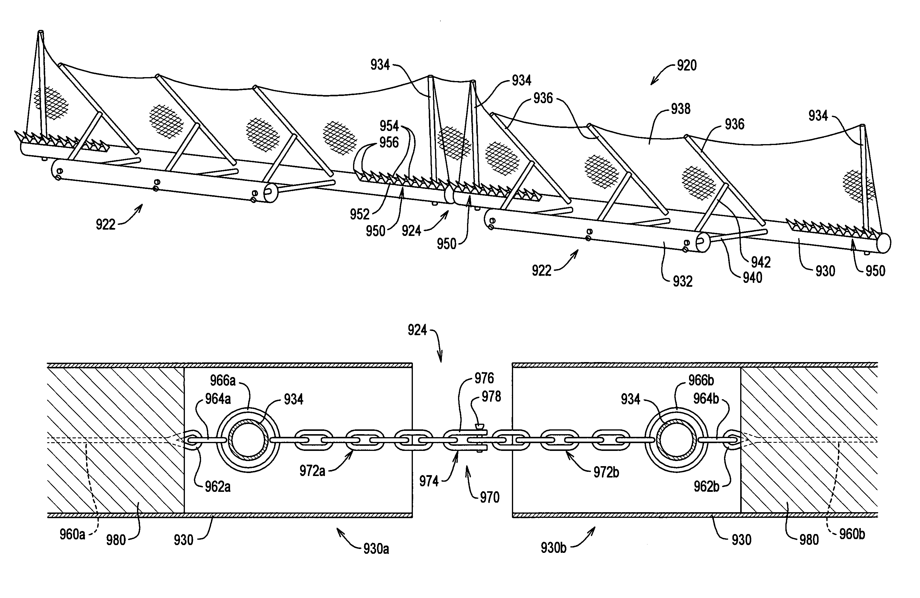
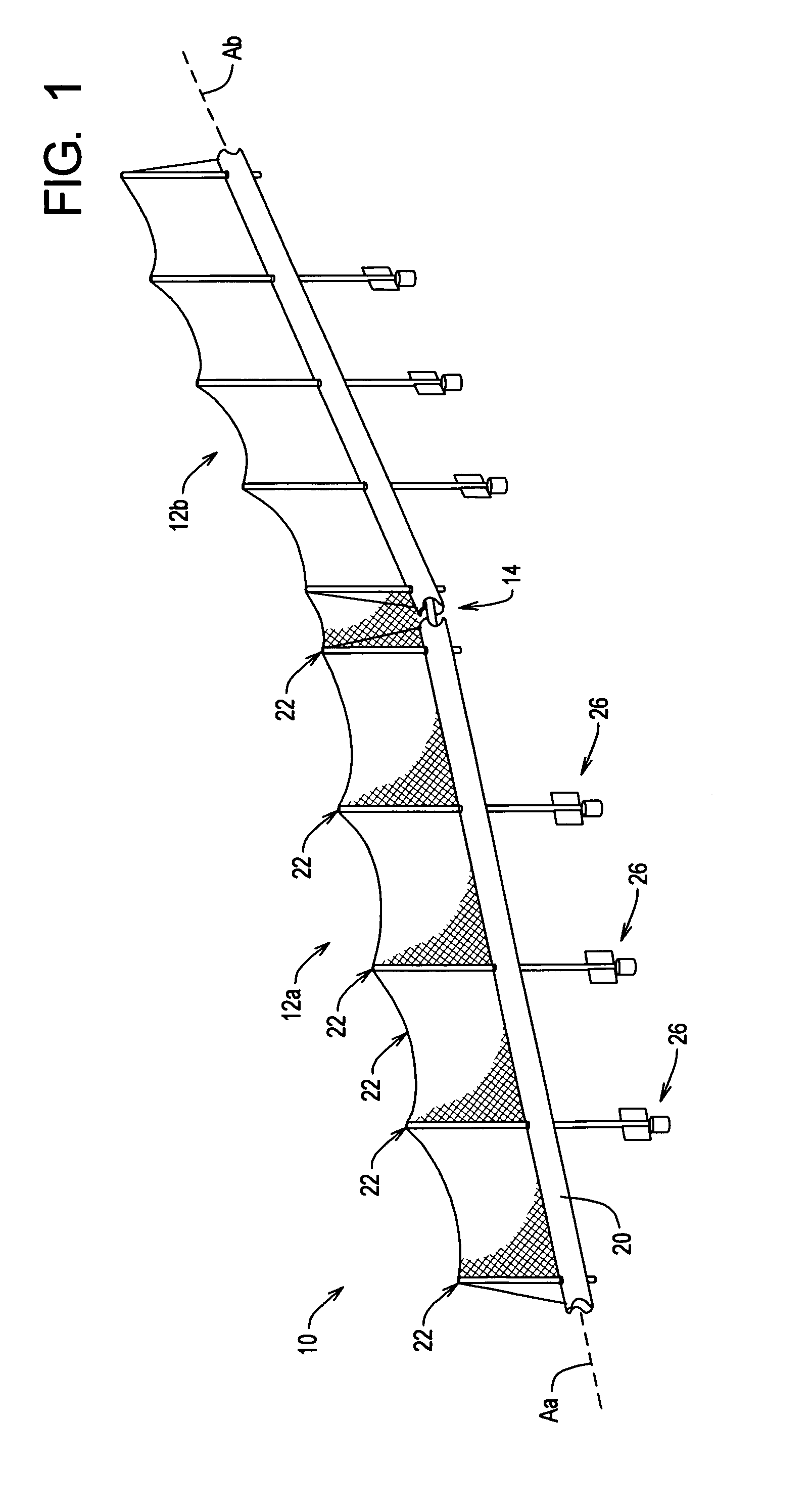
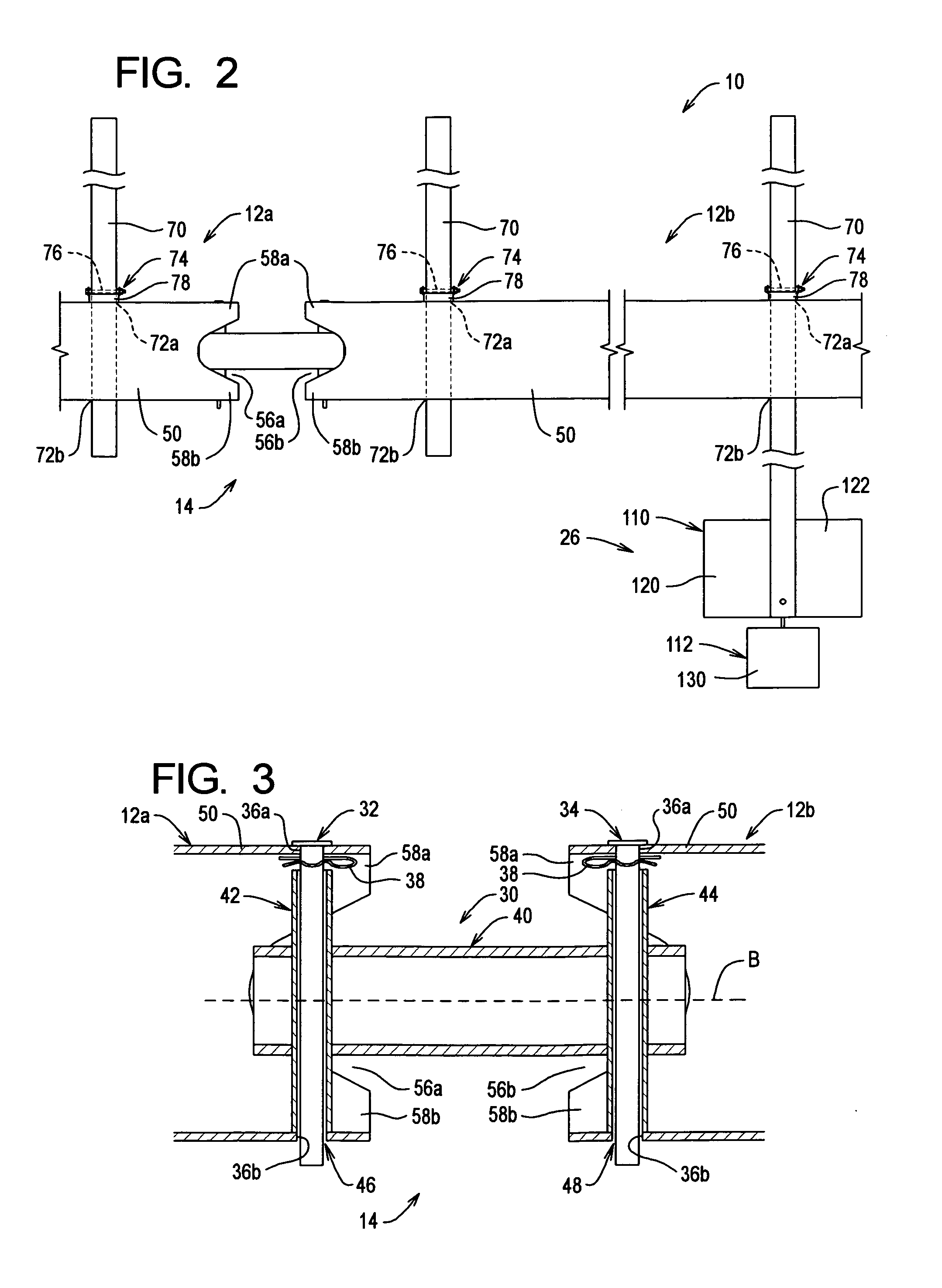
[0041]With reference to FIG. 1, a marine barrier system 10 is depicted therein. The barrier system 10 is designed to be deployed on a body of water to restrict movement on the body of water. The exemplary barrier system 10 comprises first and second barrier sections 12a and 12b connected together using a coupling system 14. Additional barrier sections 12 may be used to obtain a barrier system 10 having a longer effective length. The barrier system 10 is used to restrict access to stationary watercraft and / or onshore or offshore marine installations such as harbors, oilrigs, and the like.

[0042]The barrier system 10 may be arranged in a number of configurations depending upon the nature of the restricted site. In each configuration, the barrier system 10 will define a “barrier line” across which movement in the water is obstructed or restricted. For example, the barrier system 10 may be arranged such that the barrier line defines a closed figure that extends completely around a waterc...


PUM


Abstract

A marine barrier system comprising first and second barrier sections and a coupler system. The first and second barrier sections comprise first and second main flotation members, respectively, and each main flotation member contains buoyant material. The coupler system is arranged at the juncture of the first and second barrier sections. The coupler system is arranged such that the first and second main flotation members may be placed in a storage configuration and in a deployed configuration. In the storage configuration, the first and second main flotation members are arranged in a parallel, side by side arrangement. In the deployed configuration, the first and second main flotation members are arranged end to end to define a barrier line in a body of water across which movement is limited.

Description

RELATED APPLICATIONS[0001]This is a continuation of U.S. Ser. No. 10 / 749,849 filed Dec. 30, 2003, now Abandoned, which claims benefit of U.S. Provisional Application Ser. Nos. 60 / 437,664 filed on Dec. 31, 2002, and 60 / 485,532 filed on Jul. 7, 2003. The contents of all related applications listed above are incorporated herein by reference.TECHNICAL FIELD[0002]The present invention relates to marine barriers and, more particularly, to barrier systems and methods that may be deployed on a body of water to protect watercraft and / or marine installations.BACKGROUND OF THE INVENTION[0003]Security concerns make it desirable to limit access to watercraft and / or marine installations. For example, unauthorized persons may be prevented from boarding a docked or moored vessel relatively easily, but preventing an unauthorized person from approaching a vessel from the water can be difficult. The need thus exists for systems and methods for establishing a barrier line in the water to inhibit access...

Claims


Application Information

Patent Timeline
Patent Type & Authority Patents(United States)
IPC IPC(8): B63G9/04E02B15/06
CPCB63G9/04E02B15/08E02B15/0807E02B15/085
Inventor SPINK, RICHARD
Owner SPINK RICHARD
Learn More