Method and apparatus for shaping section bar made of composite material and shaped product and I-shaped stringer thereof

a technology of composite materials and shaped products, applied in the direction of manufacturing tools, transportation and packaging, other domestic articles, etc., can solve the problem that the forming cost of the stringer occupies about 64% of the whole manufacturing cost of the shell panel

Active Publication Date: 2006-11-28
KAWASAKI HEAVY IND LTD
View PDF14 Cites 61 Cited by
  • Summary
  • Abstract
  • Description
  • Claims
  • Application Information

AI Technical Summary

Benefits of technology

[0018]Before pressing a part of the stacked reinforced-fiber sheets to be a web portion of the stringer by the side presses, open ends of the stacked reinforced-fiber sheets are bent to the other directions, respectively, to form, for example, “base-end flange portions” to be coupled to a skin. Thus, a shaped product, such as “a T-shaped stringer,” produced thereby is high in quality, in which a distortion (“fluctuation”) of the stacked reinforced-fiber sheets in the inner side ply or plies of bending does not occur, and in which the ends of the stacked reinforced-fiber sheets are aligned between plies.
[0025]Then, after the punch is extracted, the stopper moves further up to press the looped end of the stacked reinforced-fiber sheets between the lower surfaces of the side presses to spread the looped end to both left and right while the looped end of the stacked reinforced-fiber sheets is being pierced by the positioning needle. Thereby, by disposing the positioning needle at a middle position in the left-and-right direction (in the width direction of the stacked reinforced-fiber sheets), the looped end of the stacked reinforced-fiber sheets can be equally spread to the left and right and, thus, tip-end flange portions with equal widths in the left-and-right direction can be formed.

Problems solved by technology

A forming cost of the stringer occupies about 64% of the whole manufacturing cost of the shell panel.

Method used


Image

  • Method and apparatus for shaping section bar made of composite material and shaped product and I-shaped stringer thereof
  • Method and apparatus for shaping section bar made of composite material and shaped product and I-shaped stringer thereof
  • Method and apparatus for shaping section bar made of composite material and shaped product and I-shaped stringer thereof

Examples


Embodiment Construction

[0040]Hereinafter, a method of shaping a section bar made of composite material, an apparatus utilizing the method, and a shaped product as a resultant will be illustrated according to the present invention. As an example of the shaped product, a stringer of a skin-stringer structure will be described referring to the accompanied drawings.

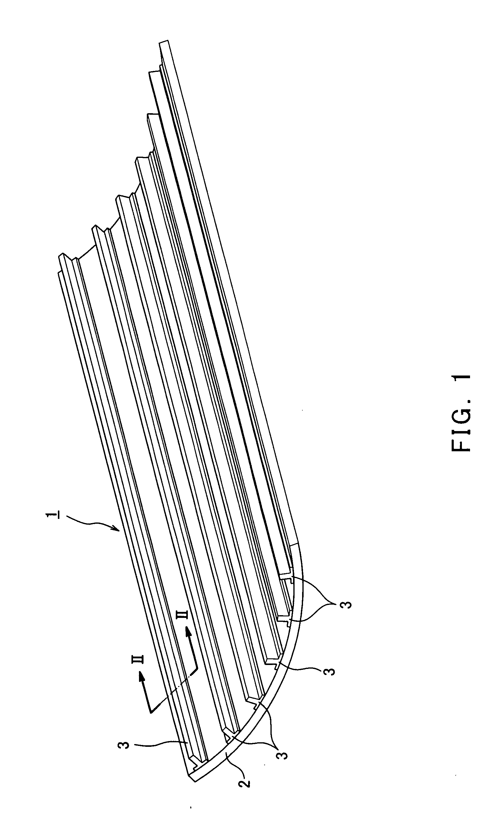
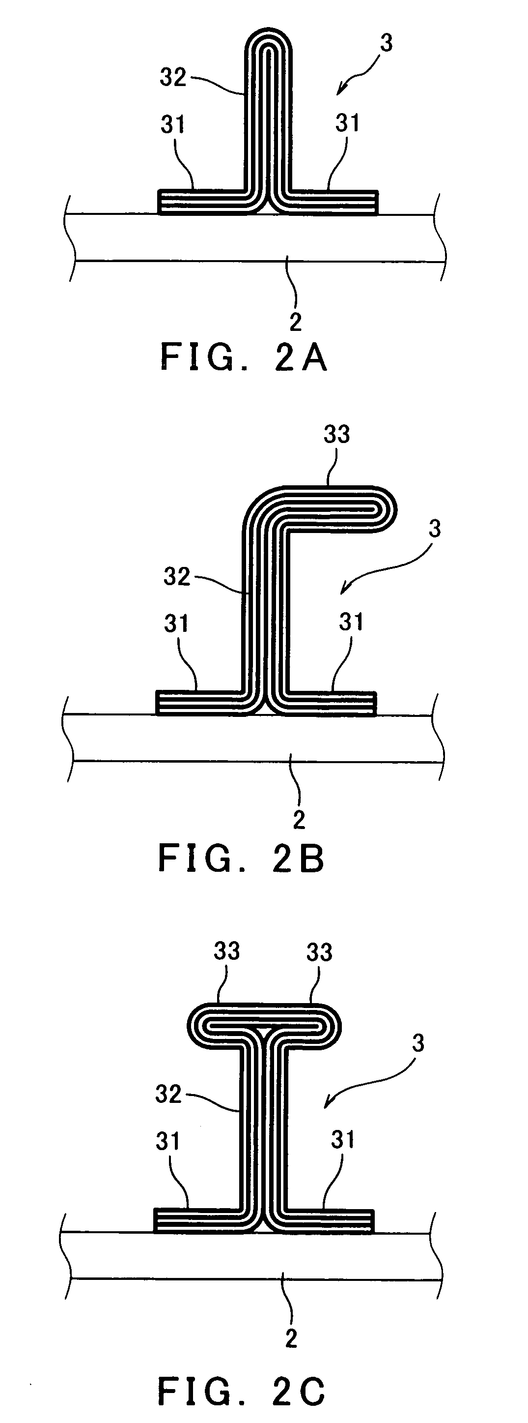
[0041]As shown in FIG. 1, a stringer 3 of this embodiment is hardened (for example, by heat) together with a skin 2 and, finally, formed to be a skin-stringer structure 1. The stringer 3 and skin 2 are made of the same material, such as prepreg. According to a shaping method of the present invention, a “T-shaped” stringer (see FIG. 2A) and a “J-shaped” stringer (see FIG. 2B) with substantially the same shapes as from a conventional method can be shaped, as well as an “I-shaped” or “H-shaped” stringer (see FIG. 2C).

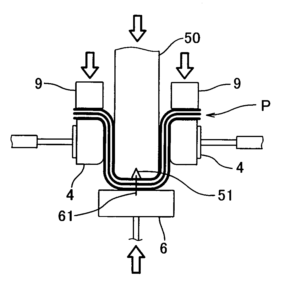
[0042]Next, the shaping methods of the T-shaped, J-shaped, and I-shaped or H-shaped stringers will be explained in detail, referring to ...


PUM

PropertyMeasurementUnit
shapeaaaaaaaaaa
dimensionaaaaaaaaaa
thicknessaaaaaaaaaa

Abstract

A method and apparatus for shaping a section bar (for example, a “T-shaped” or “J-shaped” stringer) made of composite material is provided. The method comprising the steps of placing the stacked reinforced-fiber sheets on a pair of side presses opposing to each other with a predetermined gap; inserting a punch through the gap from above to fold the stacked reinforced-fiber sheets in half, while holding ends of the stacked reinforced-fiber sheets between upper surfaces of the side presses by block members; drawing out the punch upward and then pressing the stacked reinforced-fiber sheets folded by the side presses therebetween. A shaped product shaped thereby is high quality in which a distortion (“fluctuation”) of the stacked reinforced-fiber sheets in the inner side ply or plies of bending does not occur and ends of the stacked reinforced-fiber sheets are aligned between plies.

Description

TECHNICAL FIELD[0001]The present invention relates to a skin-stringer structure having a surface-plate portion made of composite material, and a reinforcement portion made of composite material provided on a one-side-surface of the surface-plate portion and extended to one direction along the surface-plate portion. Especially, the present invention relates to a method of shaping such stringer, an apparatus used for that shaping, and a stringer as a shaped product.BACKGROUND OF THE INVENTION[0002]In recent years, the rate of use of a skin-stringer structure made of composite material as a shell panel of a fuselage or wings of an airplane has increased. A forming cost of the stringer occupies about 64% of the whole manufacturing cost of the shell panel.[0003]As shown in FIG. 1, a skin-stringer structure 1 or a shell panel made of composite material typically comprises a board-shaped skin 2 which is located on the outer fuselage and painted on an outside surface thereof, and one or mor...

Claims


Application Information

Patent Timeline
Patent Type & Authority Patents(United States)
IPC IPC(8): B29C43/20B29C70/46B29C70/06B29C70/34B29C70/54B29D99/00
CPCB29C70/345B29C70/46B29D99/0014B29C70/541Y10T428/24174B29L2031/003B29C53/04
Inventor SANA, TOSHIKAZUSATO, MAKOTO
Owner KAWASAKI HEAVY IND LTD
Why Eureka
Try Eureka