Method and device for generating clock signal

a clock signal and clock signal technology, applied in the direction of recording signal processing, frequency to phase shift conversion, instruments, etc., can solve the problems of disc production jitter, recording and reproduction of data may not be performed in a satisfactory manner, and the required clock signal cannot be generated, so as to achieve a small gain

Active Publication Date: 2006-11-28
SEMICON COMPONENTS IND LLC
View PDF1 Cites 33 Cited by
  • Summary
  • Abstract
  • Description
  • Claims
  • Application Information

AI Technical Summary

Benefits of technology

[0008]The present invention provides a method and device for generating a clock signal that is synchronized with a cycle signal including jitter even if there are manufacturing differences between voltage controlled oscillators.

Problems solved by technology

Fluctuations in the rotation of the disc or tilting of the disc may produce jitter.
As a result, the recording and reproduction of data may not be performed in a satisfactory manner.
However, there is a possibility that the required clock signal cannot be generated when voltage controlled oscillators have manufacturing differences.
Thus, if a deviation occurs in the oscillation characteristic due to manufacturing differences, when there is a request for the generation of a clock signal having a frequency corresponding to, for example, four times the disc rotation speed, there is a possibility that the voltage controlled oscillator cannot generate a clock signal with the required frequency.
As a result, the setting of the oscillation characteristic of the voltage controlled oscillator in accordance with a minimized gain makes it difficult to cope with manufacturing differences.
This may, in turn, reduce the recording and reproduction quality.
The problem caused by manufacturing differences between voltage controlled oscillators is not limited to a clock signal generation device incorporated in an optical disc device and may also occur in any clock signal generation device that generates a clock signal synchronized with a cycle signal including jitter.

Method used


Image

  • Method and device for generating clock signal
  • Method and device for generating clock signal
  • Method and device for generating clock signal

Examples


Embodiment Construction

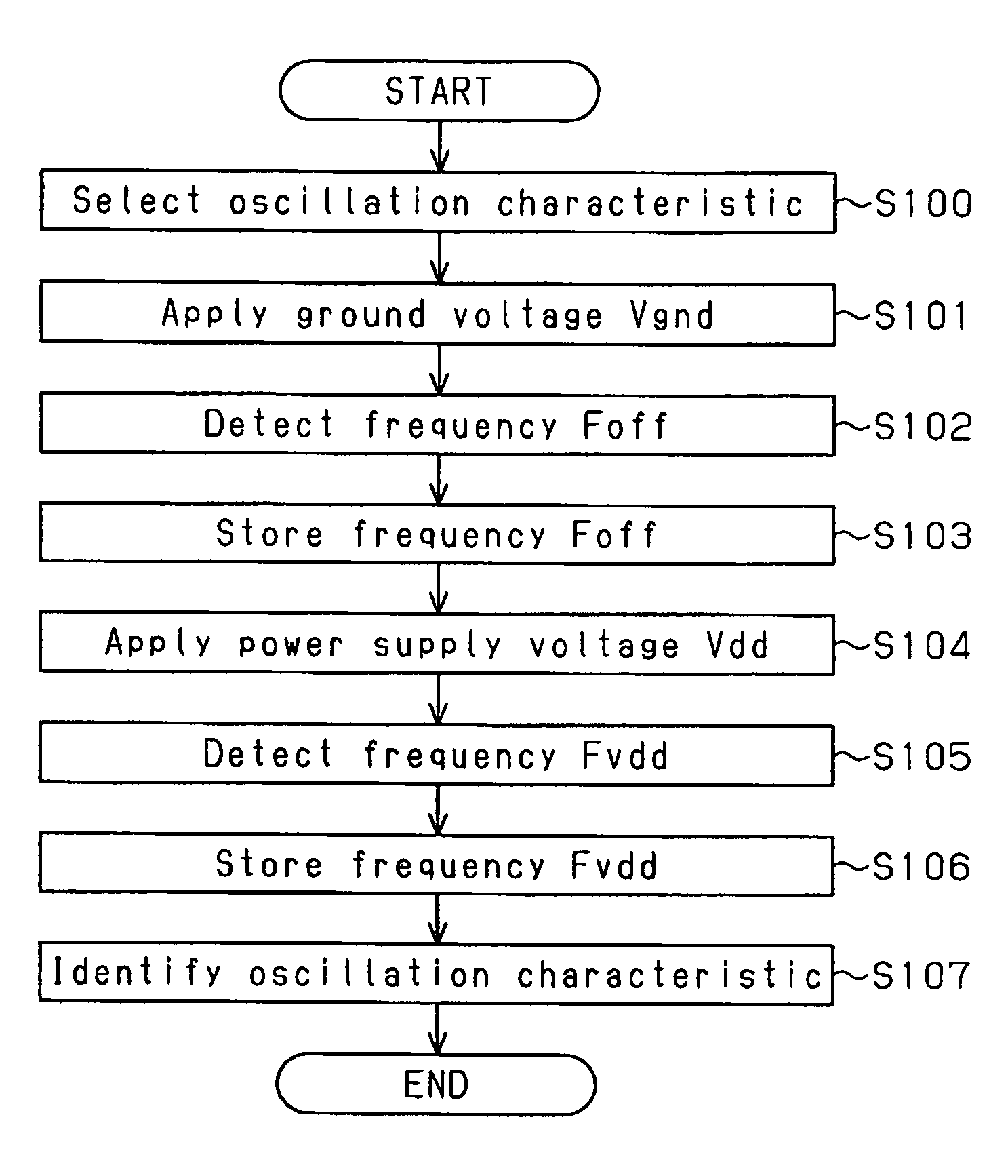
[0019]A clock signal generation device 100 according to a preferred embodiment of the present invention will now be described with reference to FIGS. 1 to 5. The clock signal generation device 100 is applied to an optical disc device capable of recording data to a DVD-R / RW disc.

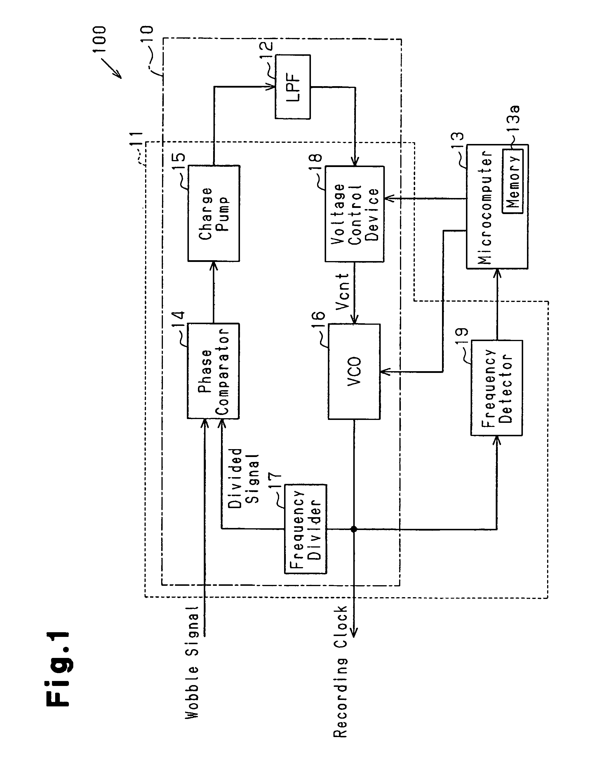
[0020]Referring to FIG. 1, the clock signal generation device 100 includes a clock signal generation circuit 11, a low pass filter (LPF) 12, and a microcomputer 13, which is connected to the clock signal generation circuit 11 and which functions as an external controller. The low pass filter 12 and part of the clock signal generation circuit 11 configure a PLL circuit 10.

[0021]The clock signal generation circuit 11 includes a phase comparator 14, a charge pump 15, a voltage controlled oscillator 16, a frequency divider 17, a voltage control device 18, and a frequency detector 19, which are all configured on the same semiconductor chip substrate.

[0022]The phase comparator 14 receives a wobble signal, which fun...


PUM

PropertyMeasurementUnit
ground voltage Vgndaaaaaaaaaa
offset frequenciesaaaaaaaaaa
frequencyaaaaaaaaaa

Abstract

A method and device for generating a clock signal accurately synchronized with a wobble signal including jitter even if there are manufacturing differences between voltage controlled oscillators. The clock signal generation device includes a voltage controlled oscillator for generating a clock signal corresponding to each of a plurality of oscillation characteristics. The clock signal generation device applies a test voltage to a voltage controlled oscillator with a voltage control device and sequentially identifies a plurality of oscillation characteristics set for the voltage controlled oscillator. The clock signal generation device selects one of the identified oscillation characteristics that has a frequency range with a generally middle part in which the frequency of a wobble signal is located and has a smaller gain.

Description

CROSS-REFERENCE TO RELATED APPLICATIONS[0001]This application is based upon and claims the benefit of priority from the prior Japanese Patent Application No. 2004-22818, filed on Jan. 30, 2004, the entire contents of which are incorporated herein by reference.BACKGROUND OF THE INVENTION[0002]The present invention relates to a method and device for generating a clock signal synchronized with an input cycle signal.[0003]In the prior art, a clock signal generation device is incorporated in, for example, an optical disc device capable of recording data to a recordable type optical disc, such as a digital versatile disc-recordable (DVD-R), to generate a recording clock signal used as a reference when recording data. The clock signal generation device normally includes a phase lock loop (PLL) circuit. A recording process is performed based on the recording clock signal generated by the clock signal generation device. Data recording is accurately performed in accordance with the rotation s...

Claims


Application Information

Patent Timeline
Patent Type & Authority Patents(United States)
IPC IPC(8): G01R19/00H03L7/093G11B20/00H03L7/06H03L7/08H03L7/087H03L7/099H03L7/18H04L27/152
CPCH03L7/087H03L7/18H03L7/099H03L7/093F16L5/02
Inventor HIRAYAMA, HIDEKIWATANABE, TOMOFUMIKIYOSE, MASASHI
Owner SEMICON COMPONENTS IND LLC
Why Eureka
Try Eureka