Microelectromechanical power generator and vibration sensor

a micro-electromechanical and power generator technology, applied in the direction of electrostrictive/piezoelectric relays, dynamo-electric machines, electrical apparatus, etc., can solve the problems of battery damage, microsensors or microsystems cannot be replaced without substantial expense or damage, previous sources of electrical power based on mechanical energy have met with limited success, etc., to achieve more efficient operation and larger voltage

Inactive Publication Date: 2006-11-28
NAT TECH & ENG SOLUTIONS OF SANDIA LLC
View PDF4 Cites 41 Cited by
  • Summary
  • Abstract
  • Description
  • Claims
  • Application Information

AI Technical Summary

Benefits of technology

[0013]In the various embodiments of the MEM apparatus of present invention above, a resonant frequency of the shuttle and the plurality of permanent magnets can be made substantially equal to a dominant resonant frequency of a vibration which produces the movement of the shuttle. When the MEM apparatus is used as an electrical power generator, this results in more efficient operation; and when the MEM apparatus is used as a vibration sensor, this results in a larger voltage being generated across the meandering electrical pickup.

Problems solved by technology

For example, microsensors or microsystems placed inside medical implantable devices or used for unattended structural monitoring often are not easily accessible so that batteries cannot be replaced without substantial expense or damage.
Previous sources of electrical power based on harvesting mechanical energy have met with limited success due to the small amount of electrical power generated, the low voltage produced, the large size of the device, or a combination of these factors.

Method used


Image

  • Microelectromechanical power generator and vibration sensor
  • Microelectromechanical power generator and vibration sensor
  • Microelectromechanical power generator and vibration sensor

Examples


Embodiment Construction

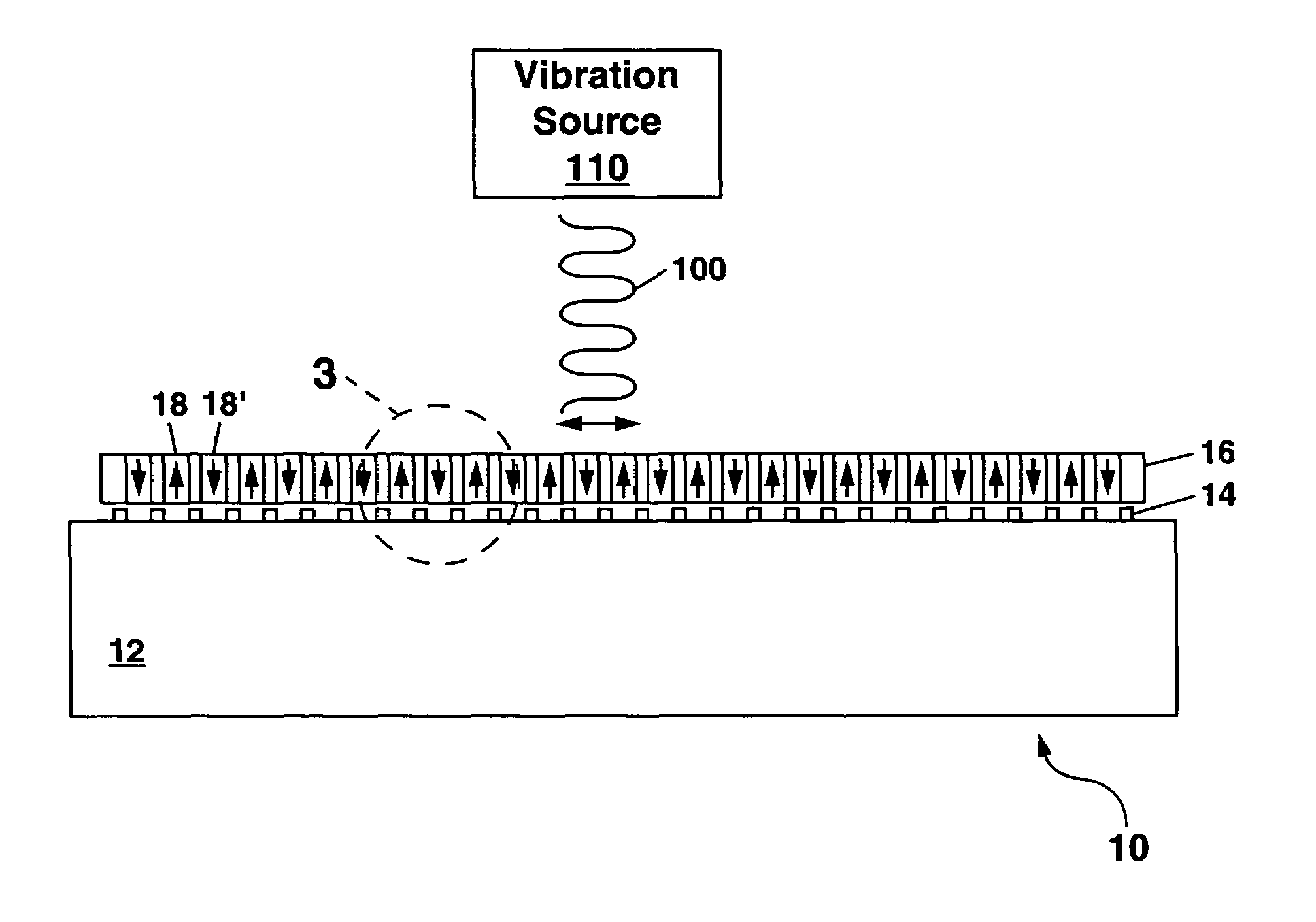
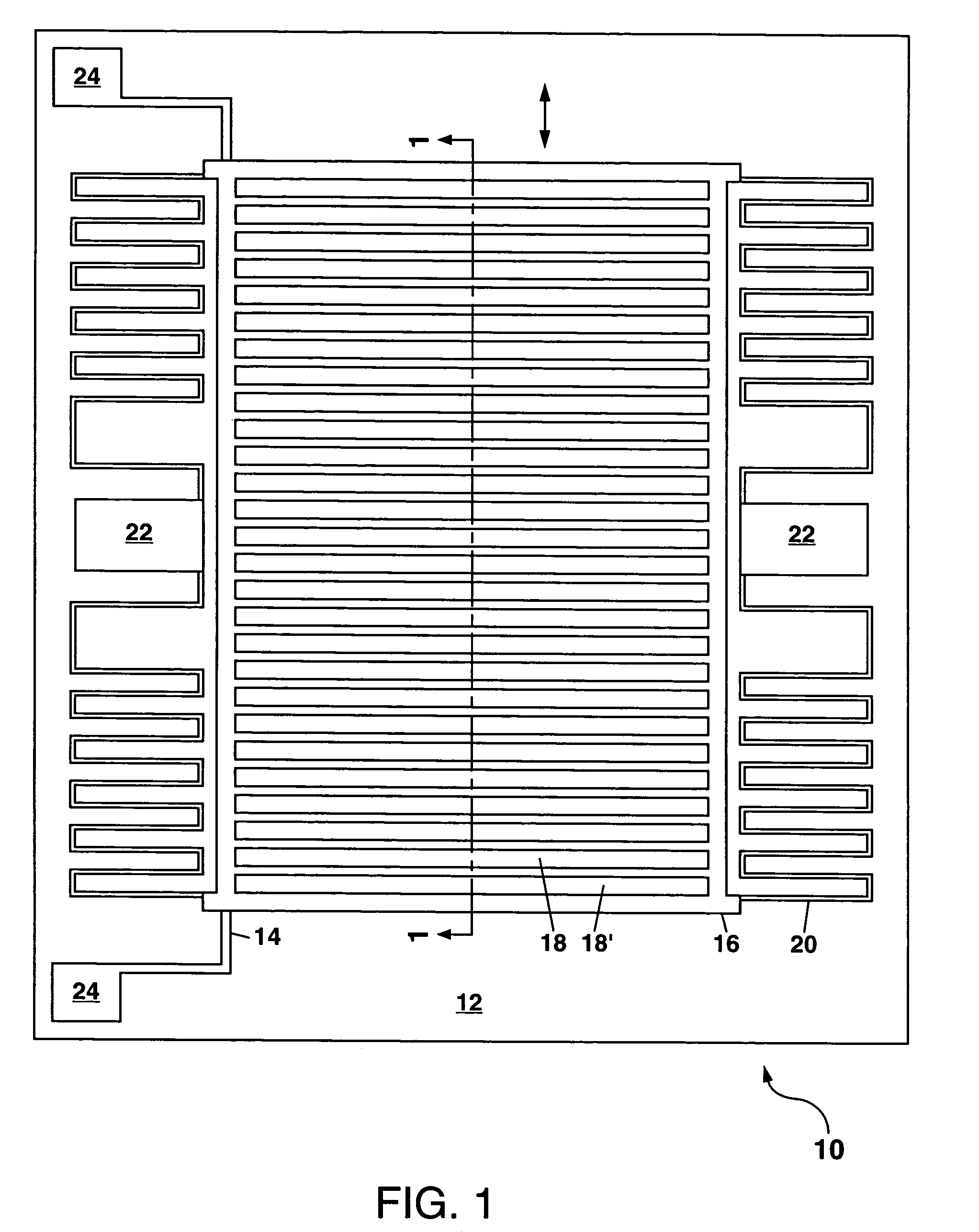
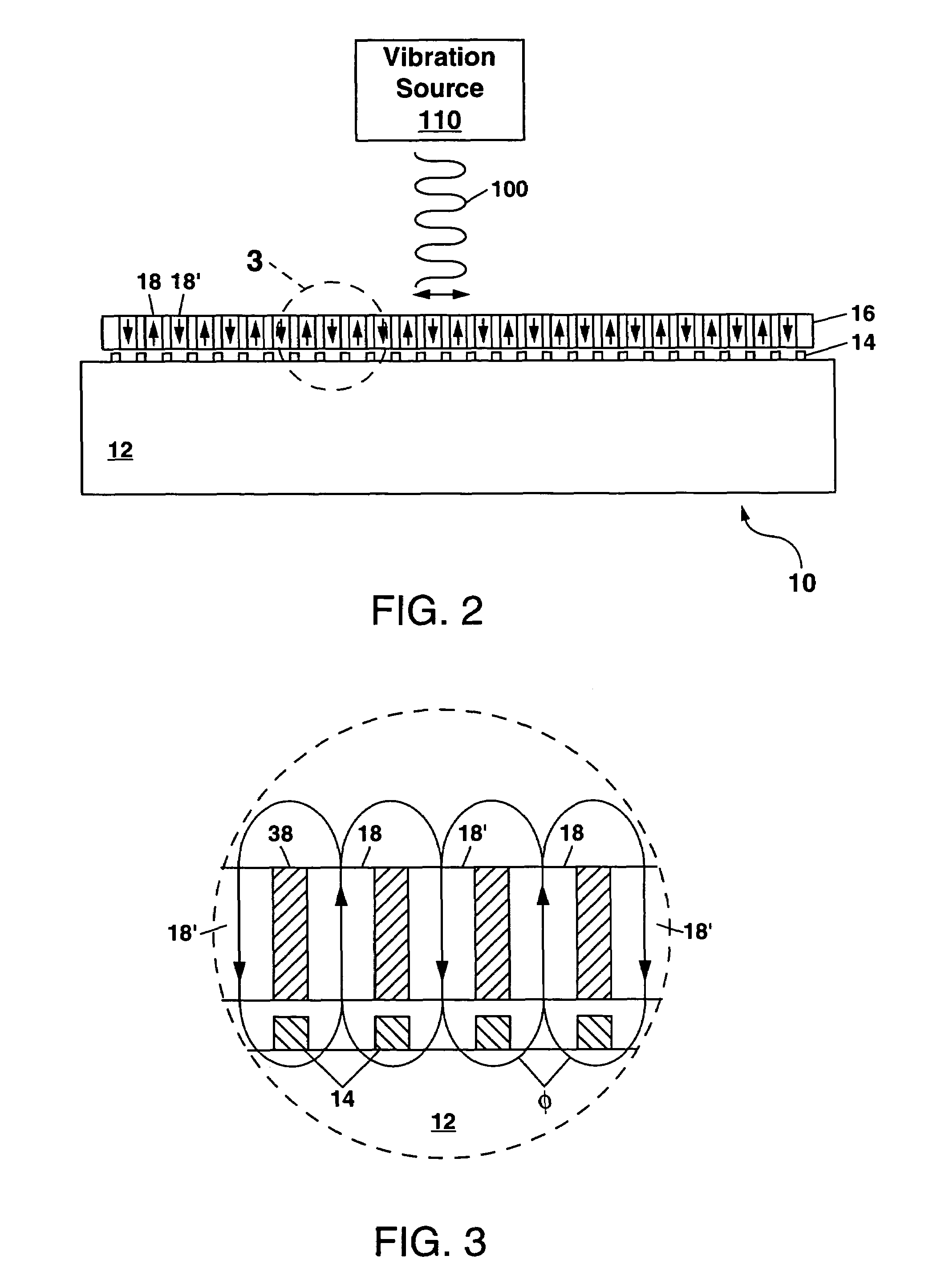
[0031]Referring to FIG. 1, there is shown a first example of a microelectromechanical (MEM) apparatus 10 which can be used as an electrical power generator, a vibration sensor, or a flux compression generator. In each case, the MEM apparatus 10 produces a voltage in response to movement of a plurality of permanent magnets therein, with the movement of the permanent magnets being in response to vibration, acceleration or impact.

[0032]The MEM apparatus 10 in FIG. 1 comprises a substrate 12 whereon a meandering electrical pickup 14 is disposed. A moveable shuttle 16 is suspended over the meandering electrical pickup 14, with the shuttle 16 holding a plurality of permanent magnets 18 and 18′ arranged side-by-side in a plane with an alternating north-south magnetic pole alignment. The phrase “north-south magnetic pole alignment” defines a line running between a north pole and a south pole of a particular permanent magnet 18 or 18′ and further indicates at which end of that line the north...


PUM


Abstract

A microelectromechanical (MEM) apparatus is disclosed which can be used to generate electrical power in response to an external source of vibrations, or to sense the vibrations and generate an electrical output voltage in response thereto. The MEM apparatus utilizes a meandering electrical pickup located near a shuttle which holds a plurality of permanent magnets. Upon movement of the shuttle in response to vibrations coupled thereto, the permanent magnets move in a direction substantially parallel to the meandering electrical pickup, and this generates a voltage across the meandering electrical pickup. The MEM apparatus can be fabricated by LIGA or micromachining.

Description

GOVERNMENT RIGHTS[0001]This invention was made with Government support under Contract No. DE-AC04-94AL85000 awarded by the U.S. Department of Energy. The Government has certain rights in the invention.CROSS REFERENCE TO RELATED APPLICATIONS[0002]This application is related to co-pending application Ser. No. 10 / 817,007 entitled “Method for Forming Permanent Magnets with Different Polarities for Use in Microelectromechanical Devices” filed on Apr. 1, 2004.FIELD OF THE INVENTION[0003]The present invention relates in general to microelectromechanical (MEM) devices, and in particular to MEM devices which include a plurality of permanent magnets and which are responsive to vibrations to generate an electrical voltage for producing electrical power, for sensing the presence of the vibrations, or for sensing a sudden acceleration or impact.BACKGROUND OF THE INVENTION[0004]Microelectromechanical (MEM) fabrication technologies such as surface and bulk micromachining and LIGA (an acronym based...

Claims


Application Information

Patent Timeline
Patent Type & Authority Patents(United States)
IPC IPC(8): H01H51/22
CPCH02K35/02
Inventor ROESLER, ALEXANDER W.CHRISTENSON, TODD R.
Owner NAT TECH & ENG SOLUTIONS OF SANDIA LLC
Why Eureka
Try Eureka