Laser digitizer system for dental applications

a digital camera and dental technology, applied in the field of three-dimensional imaging of physical objects, can solve the problems of limiting the speed at which the system may acquire sufficient data to generate a 3d image, inaccuracy of reading the depth of field and uniformity of a line width, and inconvenient operation

Inactive Publication Date: 2006-11-28
D4D TECH LP
View PDF139 Cites 125 Cited by
  • Summary
  • Abstract
  • Description
  • Claims
  • Application Information

AI Technical Summary

Problems solved by technology

Such scanning may also result in an inaccurate reading of depth of field and uniformity of a line width due to the scanned arc.
However, some special optics adversely effect and distort the optical image and limit the speed at which the system may acquire sufficient data to generate a 3D image.
However, the intensity of the laser line(s) may vary along the length of the projected line(s), resulting in inaccurate measurements and imaging of the object.
The laser line systems are also susceptible to laser speckle, which may appear as a mottled pattern of randomly distributed “blobs of light.” Laser speckle may be caused by an interference at the image plane of coherent light reflected by a rough surface.
The mottled pattern may introduce noise and uncertainty into the measurement, due to a difficulty in distinguishing between useful intensity data, and speckle intensity data.
Current laser systems used in dental applications may be rudimentary and limited by the projection of a single laser line.
Such systems are not adjustable for a desired line pattern and lack any correction or minimization of a non-flat or non-linear scanning field or correction for laser speckle.
Also, such systems may have a limited clamping and holding mechanism which limit the range of molds or castings for which the digitizer may be used.

Method used


Image

  • Laser digitizer system for dental applications
  • Laser digitizer system for dental applications
  • Laser digitizer system for dental applications

Examples


Embodiment Construction

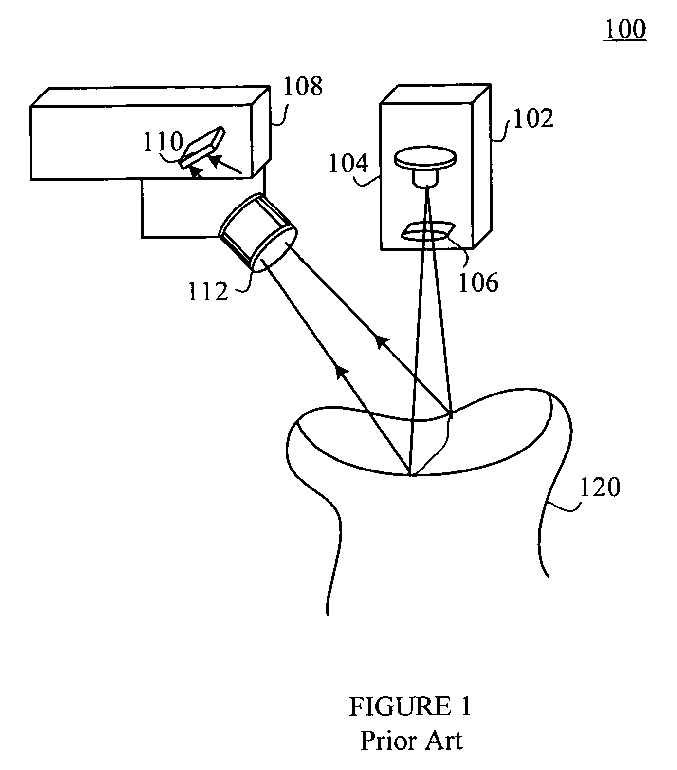
[0022]FIG. 1 illustrates an example of a prior art laser line imaging system 100. The prior art laser line imaging system 100 has a transmitter 102 and a receiver 108. The transmitter 102 includes a laser light source 104 and transmission optics 106. The transmitter 102 projects a planar laser light on an object 120 within a field of view of the transmitter 102. The planar laser light incident on the object forms a straight line on the object 120. The projected laser line is produced by either a cylindrical lens or diffractive optical element 106.

[0023]The light reflected from the object 120 is detected by the camera 108. The camera 108 has an optical axis at a known angle to the transmitter 102. The light is picked up by an optical lens 112 which focuses the reflected light onto a matrix of photo-detectors 110. The contour of the object 120 having differences in the elevation can be imaged based on the image projected on the matrix of photo-detectors 110.

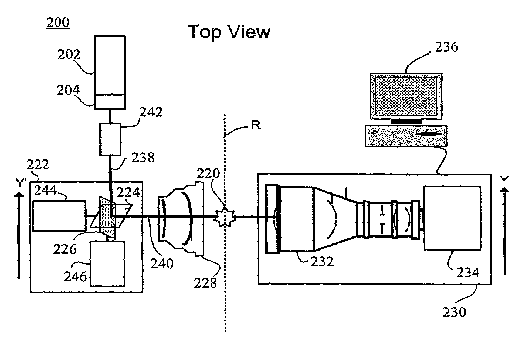
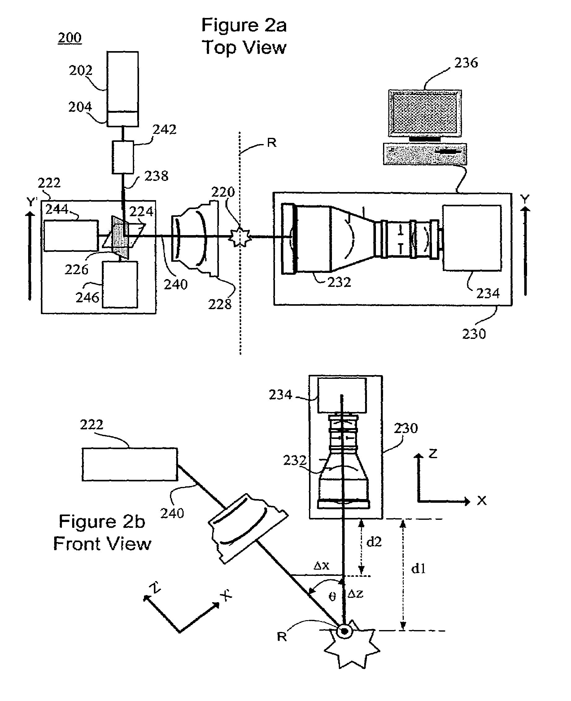
[0024]FIGS. 2a and 2b illus...


PUM


Abstract

A laser digitizer system provides a visual three-dimensional image of a real-world object such as a dental item through a laser digitization. The laser digitizer captures an image of the object by scanning multiple portions of the object in an exposure period.

Description

PRIORITY AND CROSS REFERENCE TO RELATED APPLICATION[0001]This application claims the benefit under 35 U.S.C. § 119(e) of co-pending provisional application Ser. No. 60 / 437,373 filed Dec. 31, 2002, which is incorporated in its entirety herein by reference.BACKGROUND OF THE INVENTION[0002]1. Related Field[0003]The invention relates to three-dimensional imaging of physical objects. In particular, the invention relates to laser imaging of dental items including molds, castings, dentition, prepared dentition and the like.[0004]2. Description of the Related Art[0005]Techniques have been developed to generate three-dimensional (“3D”) visual images of physical objects. The 3D image may be generated by a computer that processes data representing the surfaces and contours of a physical object. The computer displays the 3D image on a screen or a computer monitor. The data may be generated by optically scanning the physical object and detecting or capturing the light reflected off of the object...

Claims


Application Information

Patent Timeline
Patent Type & Authority Patents(United States)
IPC IPC(8): G01B11/24A61C5/00G01B11/30G06K9/00A61C9/00A61C13/00G01B11/25
CPCG01B11/24G01B11/2518A61C9/004A61C13/0004A61C9/0053
Inventor QUADLING, HENLEYQUADLING, MARKBLAIR, ALAN
Owner D4D TECH LP
Why Eureka
Try Eureka