Antenna device with a first and second antenna

Inactive Publication Date: 2006-11-28
PANASONIC CORP
View PDF10 Cites 74 Cited by
  • Summary
  • Abstract
  • Description
  • Claims
  • Application Information

AI Technical Summary

Benefits of technology

[0012]In the above-described construction, signals received from the first antenna matched with the first, second, and third frequency bands are distributed by the diplexer into signals of the first frequency band and signals of the second and third frequency bands. For signals of the first frequency band, the first switch unit selects the first receiver or first transmitter and connects the same to the diplexer. In addition, for signals of the second frequency band, the second switch unit selects the second receiver or second transmitter and connects the same to the diplexer. For signals of the third frequency band, the third switch unit selects the second antenna or diplexer and connects the same to the transmitter / receiver. Thereby, an antenna device which corresponds to two radio communications systems and three frequency bands, which can simultaneously carry out a reception and a transmission of different radio communications systems, and which is capable of using antenna diversity can be provided by a simple construction. Namely, two antenna systems corresponding to the three frequency bands composed of a dual-band single-mode antenna system of the first and second frequency bands and a single-mode antenna system of the third frequency band can be realized without making drastic modifications. In addition, a reception of signals of the first frequency band and a transmission of signals of the third frequency band can be simultaneously carried out. Furthermore, for signals of the third frequency band, an antenna device capable of using antenna diversity can be simply provided.
[0020]According to the above-described construction, an antenna device which corresponds to two radio communications systems and four frequency bands, which can simultaneously carry out a reception and a transmission of different radio communications systems, and which is capable of using antenna diversity can be provided by a simple construction. Namely, two antenna systems corresponding to the four frequency bands composed of a tri-band single-mode antenna system of the first, second, and fourth frequency bands and a single-mode antenna system of the third frequency band can be realized without making drastic modifications. In addition, a reception of signals of the first frequency band and a transmission of signals of the third frequency band can be simultaneously carried out. Furthermore, for signals of the third frequency band, an antenna device capable of using antenna diversity can be simply provided.

Problems solved by technology

However, the conventional antenna devices have had the following problems, and an improvement thereof has been demanded.

Method used


Image

  • Antenna device with a first and second antenna
  • Antenna device with a first and second antenna
  • Antenna device with a first and second antenna

Examples


first embodiment

(First Embodiment)

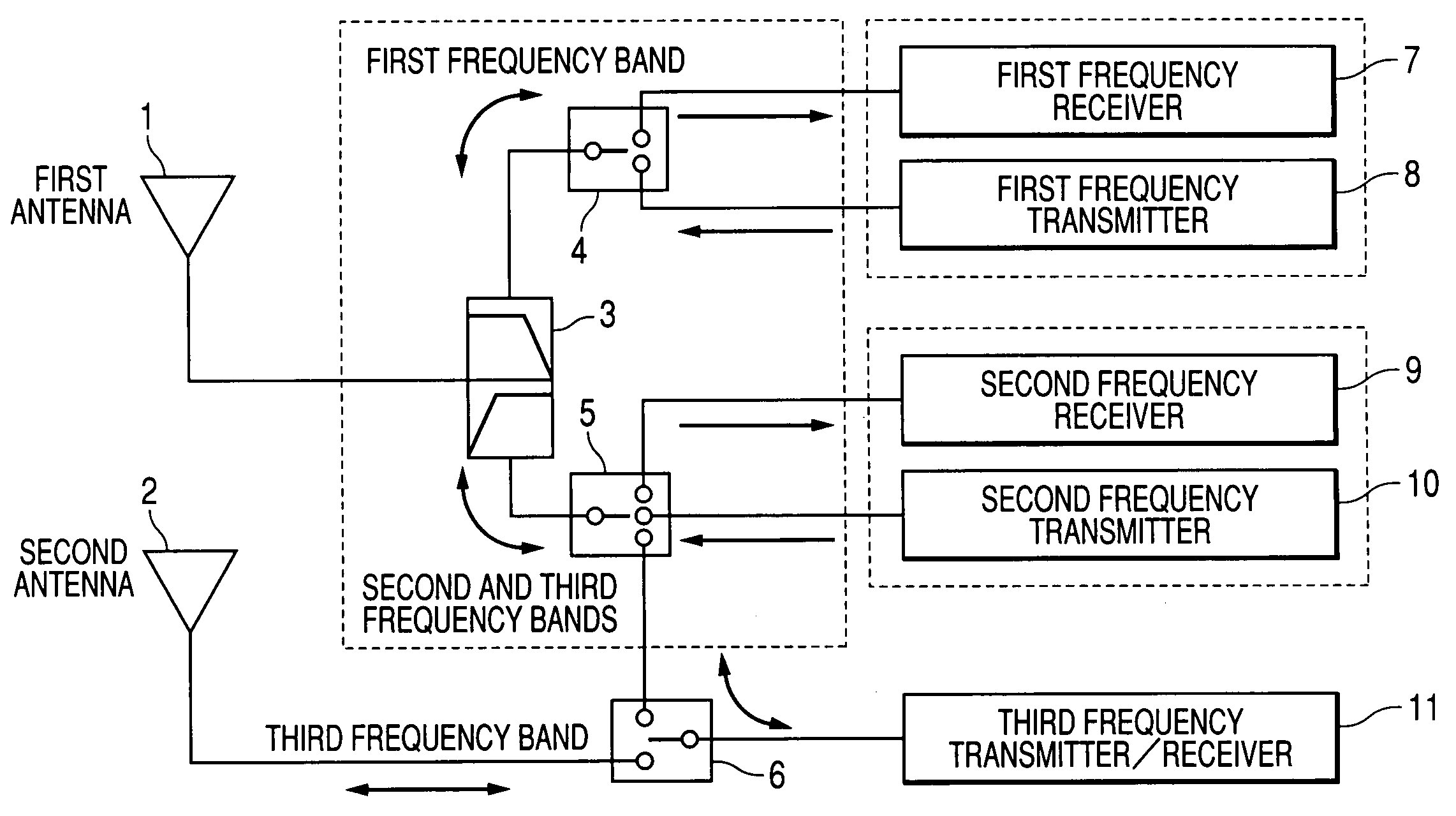
[0041]FIG. 1 is a diagram showing a construction of radio communications equipment to which an antenna device of a first embodiment has been applied. This radio communications equipment includes a first antenna 1, a second antenna 2, a diplexer 3, a first high-frequency switch circuit 4, a second high-frequency switch circuit 5, a third high-frequency switch circuit 6, a first frequency receiver 7, a first frequency transmitter 8, a second frequency receiver 9, a second frequency transmitter 10, and a third frequency transmitter / receiver 11. The antenna device of the first embodiment is constructed by including the first antenna 1, second antenna 2, diplexer 3, first high-frequency switch circuit 4, second high-frequency switch circuit 5, and third high-frequency switch circuit 6,

[0042]The first antenna 1 is matched with first, second, and third frequency bands. The second antenna 2 is matched with the third frequency band. The diplexer 3 distributes signals from t...

second embodiment

(Second Embodiment)

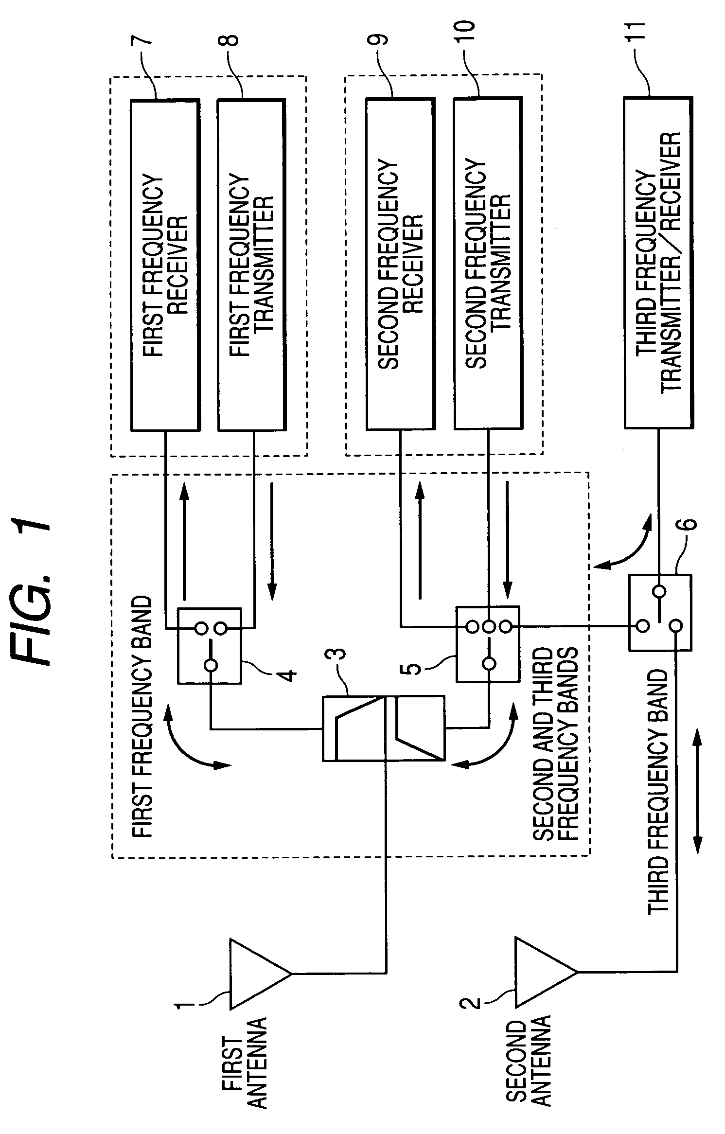
[0055]FIG. 2 is a diagram showing a construction of radio communications equipment to which an antenna device of a second embodiment has been applied. Since the antenna device of the second embodiment has almost the same construction as that of the first embodiment, identical symbols to those of the first embodiment are used for identical component parts, whereby description thereof will be omitted, and herein description will be given of only different component parts.

[0056]Namely, the antenna device of the second embodiment has an antenna switching connector 12, and the construction and operations except for this antenna switching connector are the same as those of the first embodiment. To the antenna switching connector 12, a cable plug (unillustrated) connected to an external antenna is freely attached, and the antenna connector 12 switches connection so as to connect, when this cable plug is attached, the external antenna and a diplexer 3 and, when no cable p...

third embodiment

(Third Embodiment)

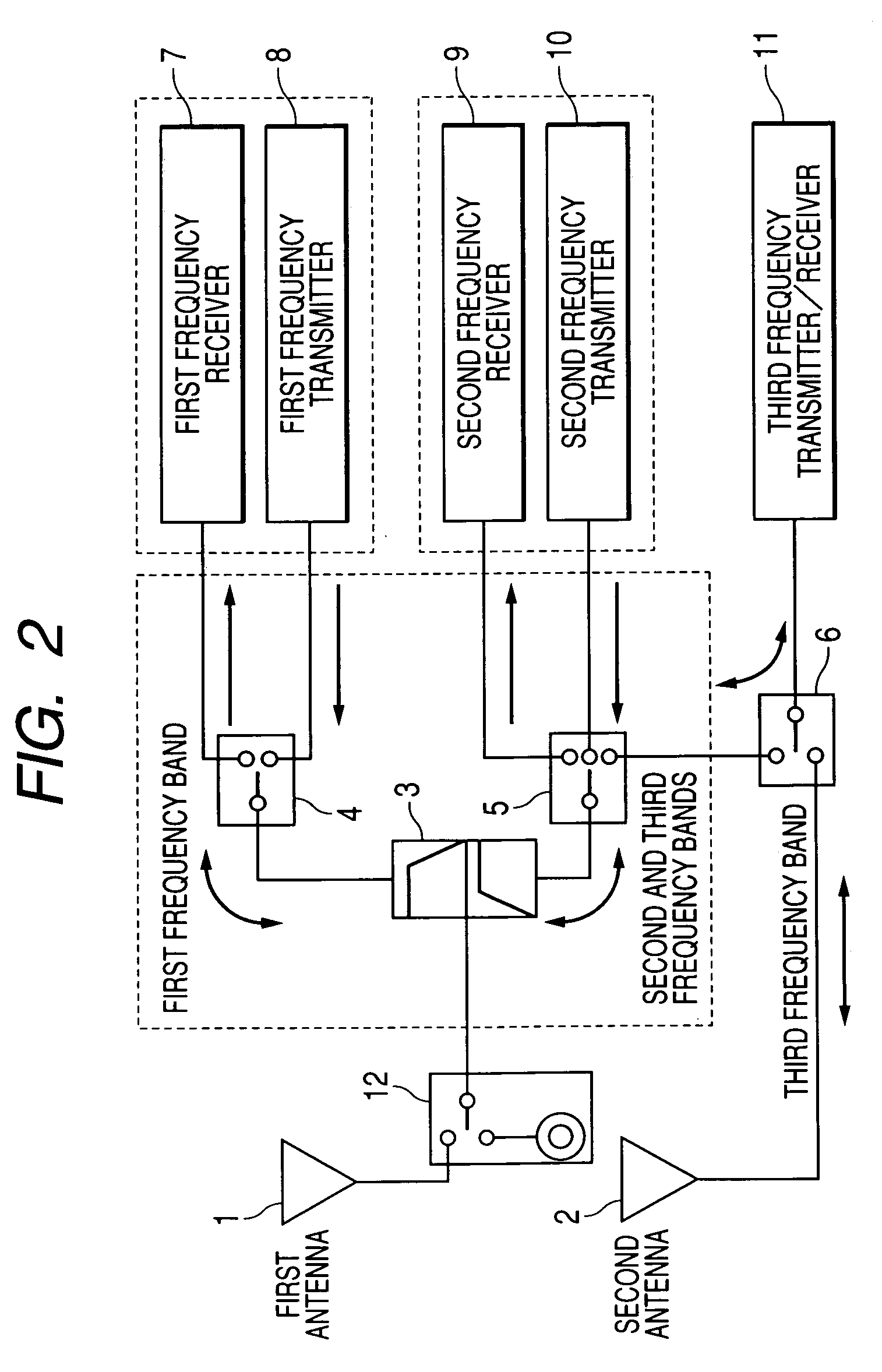
[0059]FIG. 3 is a diagram showing a construction of radio communications equipment to which an antenna device of a third embodiment has been applied. The antenna device of the third embodiment is, in addition to having the same construction as that of the first embodiment, provided with, at an output side of a first frequency transmitter 8 for transmitting signals of a first frequency band and at an output side of a second frequency transmitter 10 for transmitting signals of a second frequency band, lowpass filters 13 and 14 to suppress their respective higher harmonics. The construction and operations except for these lowpass filters 13 and 14 are the same as those of the first embodiment.

[0060]Namely, since output signals of the first frequency transmitter 8 and output signals of the second frequency transmitter 10 and transmitted from the first antenna while respective higher harmonic components thereof are suppressed, for transmitting signals of the first frequ...


PUM


Abstract

An antenna device corresponds to a plurality of radio communications systems and frequency bands, can simultaneously carry out a reception and a transmission of different radio communications systems, and is capable of using antenna diversity by a simple construction. An antenna device comprises a first antenna matching with first, second, and third frequency bands, a second antenna matching with the third frequency band, a diplexer and the like. For signals of the first frequency band, a high-frequency switch circuit connects a transmitter or a receiver to the diplexer by switching. For signals of the second frequency band, an additional high-frequency switch connects a receiver or a transmitter to the diplexer by switching. For signals of the third frequency band, the additional high-frequency switch circuit and a further additional high-frequency switch circuit connect the second antenna or diplexer to a transmitter / receiver by switching.

Description

TECHNICAL FIELD[0001]The present invention relates to an antenna device which is used for mobile communications and which is capable of corresponding to a plurality of frequency bands and a plurality of modulation schemes.BACKGROUND ART[0002]In recent years, in mobile communications systems represented by mobile telephone systems, the analogue modulation scheme of the first generation has gradually shifted to a digital modulation scheme of a second generation, and still, to a third generation which realizes high data transfer rates and can be used globally seamlessly.[0003]And, for the transition periods between the generations, multi-mode or multi-band radio communications equipment which can correspond to, in addition to the respective existing radio communications systems, new radio communications systems becomes necessary. Furthermore, in such radio communications equipment, an antenna device which can correspond to a plurality of frequency bands has been required.[0004]For exam...

Claims


Application Information

Patent Timeline
Patent Type & Authority Patents(United States)
IPC IPC(8): H04B1/44H01Q1/24H01Q21/30H01Q21/28H04B7/04H04B7/12
CPCH01Q1/241H01Q21/28H04B7/04H04B7/12
Inventor KOJIMA, NORIHARUWATANABE, HIDEKI
Owner PANASONIC CORP
Why Eureka
Try Eureka