Dynamic operator functions based on operator position

a dynamic operator and operator technology, applied in the field of industrial control systems, can solve the problems of high labor intensity, high cost, and inability to meet the needs of operators, and achieve the effect of reducing time and increasing interactivity

Inactive Publication Date: 2006-11-28
ABB (SCHWEIZ) AG
View PDF14 Cites 59 Cited by
  • Summary
  • Abstract
  • Description
  • Claims
  • Application Information

AI Technical Summary

Benefits of technology

[0027]Therefore, the use of above-mentioned communication system provides the operator the ability to remotely interact with the central control system. The invention also allows this interaction to be tailored for a particular operator and process section. This invention also provides a higher degree of interactivity, such as voice-enabled communication, between the operator and the central control system. The invention thus leads to significant reductions in the time required to carry out normal production operations as well as to gather, analyse and troubleshoot processes in the industrial plant.

Problems solved by technology

Manufacturing and process industries have become quite complex during the last few decades.
Since these individual machines are connected so intricately, a small variation in the output of one machine (or of an equipment) can easily result in malfunction of another machine or can even result in the final product being unacceptable.
Clearly such distributed control systems require a lot of human effort and are costly.
Also, since it takes substantial time for the operator to gather, collate and interpret the data, such systems are not able to handle emergency situations.
However, even in these automated systems, situations arise when an operator would have to physically visit a site and inspect a machine, a sub-system or an entire system, change set points or make other adjustments during times of ordinary production or process flow.
In addition, inspections may also be un-scheduled and some may even arise because of emergencies.
One frequent example of such an un-scheduled inspection is when the operator suspects that certain monitoring equipment—such as a pressure sensor—is malfunctioning.
This implementation suffers from two major drawbacks.
The first drawback is that one terminal has to be provided for each machine to be monitored; hence, thousands of such terminals are required and this may render the entire solution economically infeasible (especially, if these terminals are being used only for infrequent inspections).
The second major drawback is that in order to retrieve the information from other machines or from connected systems, the terminal may have to query the central process control system many times; consequently, a large number of such queries may result in over-loading of the central process control system.
In today's automated industries, and unmanned process sections, it may not be feasible to provide each process section with a computer system and terminal, since these would not be utilized frequently.
These devices are generally remote from the central process control system.
The processes and systems in manufacturing and processing industries are becoming increasingly more complex.
For these systems, the status information is often very complicated and still has to be interpreted in a short period of time.

Method used


Image

  • Dynamic operator functions based on operator position
  • Dynamic operator functions based on operator position
  • Dynamic operator functions based on operator position

Examples


Embodiment Construction

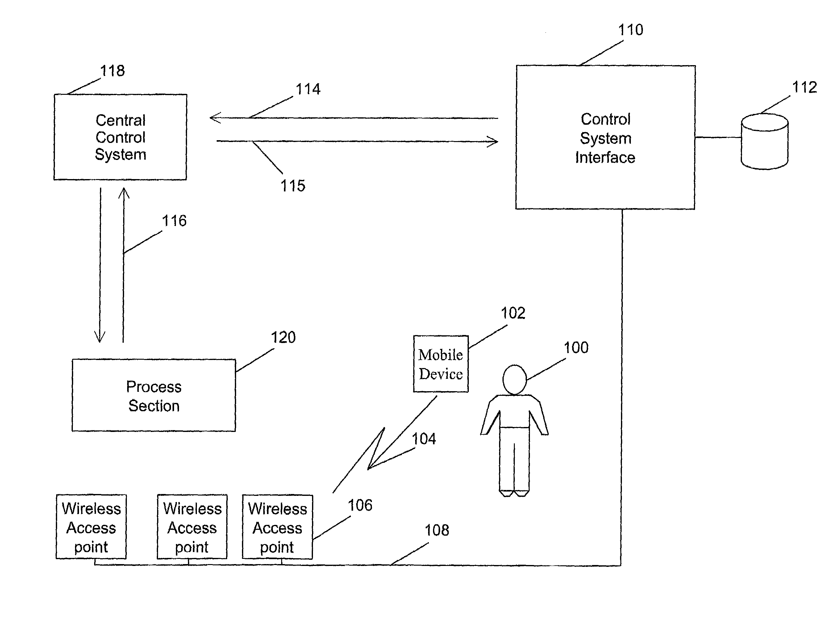
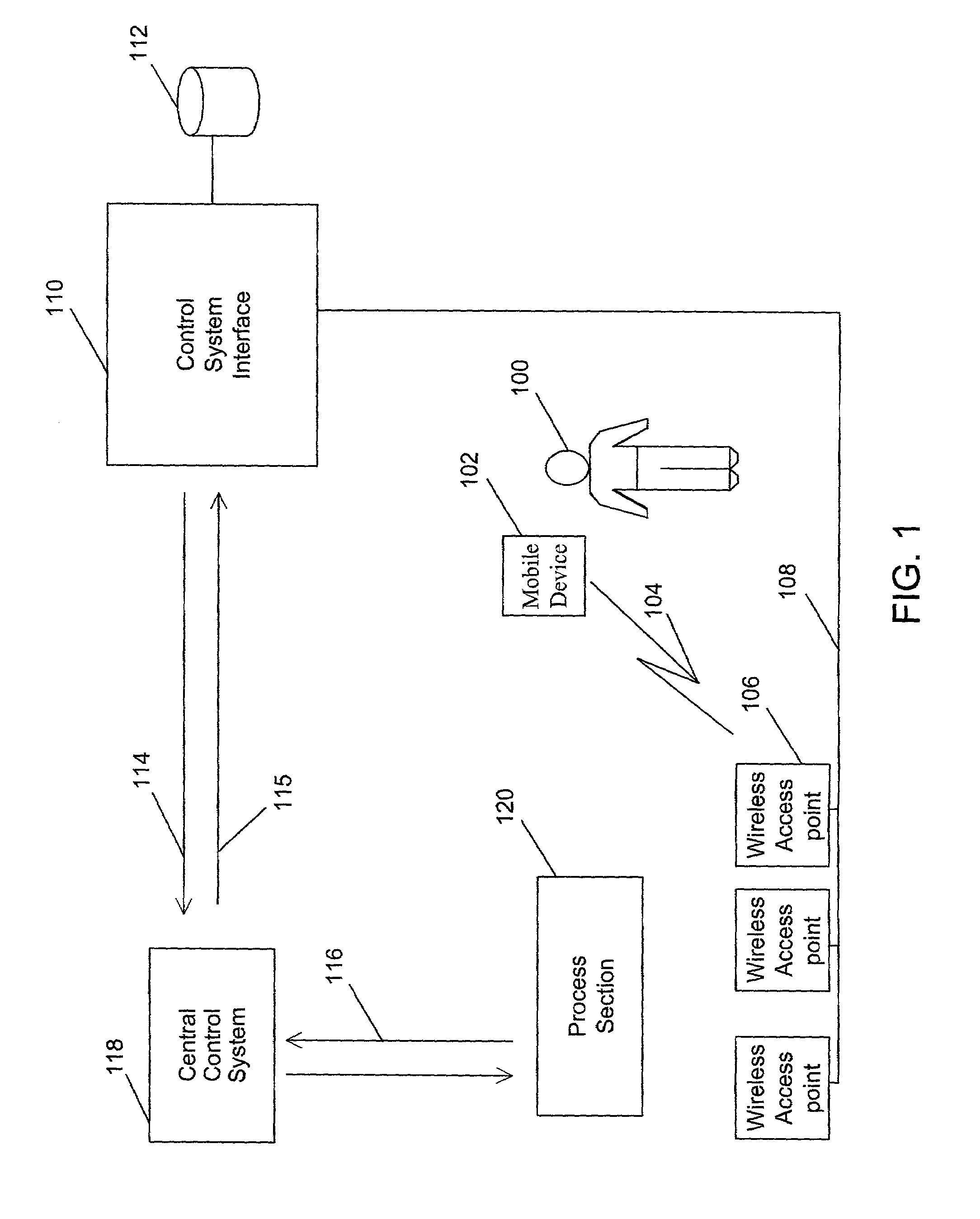
[0035]FIG. 1 is a block diagram showing an operator remotely accessing process sections in an industrial plant. A manufacturing or process industry contains many process sections and one such process section 120 is shown in FIG. 1. A process section may be a large section such as a production line, a bleaching plant or a paper machine or a small section of a process such as a single apparatus. There are many machines and / or sub-systems in a process section 120 that are interconnected to execute a specific process. In most industries, there is a central control system 118 to control and monitor process sections 120. The central control system 118 co-ordinates and controls various process sections 120 over a data network. The data network is usually a wired LAN connecting the process sections 120 to the central control system 118. The central control system 118 receives status information 116 from the process sections 120 and sends control instructions for the process section over the...


PUM


Abstract

A communication system that enables an operator to remotely query and control the process sections in an industrial plant by exchanging data with a central computer that controls the process sections. The operator communicates with the process sections through a mobile wireless device remotely connected with one of the multiple wireless access points on a data network. This data network is, in turn, connected to the central computer that controls these process sections. The central computer stores the location of the process sections and the operator profiles. When requested, it collates and processes this data and presents it to the operator. Further, if the need arises, the central computer tracks and interacts with the operator.

Description

BACKGROUND OF THE INVENTION[0001]1. Field of the Invention[0002]The present invention relates to industrial control systems. More specifically, this invention relates to providing an operator with an interactive mobile wireless unit in order to communicate remotely with the industrial control system.[0003]2. Description of Related Art[0004]Manufacturing and process industries have become quite complex during the last few decades. Today, even a small manufacturing plant can easily contain several hundreds to several thousands of manufacturing and processing machines. These machines are usually connected to each other intricately to form sub-systems, which in turn, are connected to form larger systems, and so on, until together they form the entire plant. Since these individual machines are connected so intricately, a small variation in the output of one machine (or of an equipment) can easily result in malfunction of another machine or can even result in the final product being unacc...

Claims


Application Information

Patent Timeline
Patent Type & Authority Patents(United States)
IPC IPC(8): G06F15/16H04L12/28H04L12/56H04L29/08
CPCH04W4/02H04W4/028H04L67/12H04L67/18H04L69/329G05B2219/31162H04W84/00H04W84/12H04W84/22H04W88/08H04W4/029H04L67/52
Inventor OBERG, PIERREFREY, JAN-ERIK
Owner ABB (SCHWEIZ) AG
Why Eureka
Try Eureka