Supercharge Your Innovation With Domain-Expert AI Agents!

Valve timing control system for internal combustion engine

a timing control system and internal combustion engine technology, applied in the direction of machines/engines, non-mechanical valves, couplings, etc., can solve the problems that the valve timing control system cannot be used, and the engine restart cannot be smoothly carried ou

Active Publication Date: 2006-12-05
HITACHI ASTEMO LTD
View PDF9 Cites 10 Cited by
  • Summary
  • Abstract
  • Description
  • Claims
  • Application Information

AI Technical Summary

Benefits of technology

The present invention provides a valve timing control system for an internal combustion engine that allows for effective use of the phase area shifted to the more advanced or retardant position with respect to the rotation phase which allows engine start. The system includes a phase alteration mechanism and an operation control device that can control the movement of the movable portion of the mechanism. The system can set the rotation phase at a middle position between a maximum retard position and a maximum advance position when the movable portion is located at the beginning. This results in improved engine performance and efficiency.

Problems solved by technology

Specifically, if the rotation phase which allows engine start is set at a middle position between the maximum retard position and the maximum advance position, engine restart cannot be carried out smoothly due to impossible natural returning of the rotation phase to the middle position at engine start or during inertia rotation after engine stop.
Thus, the typical valve timing control system does not allow, during engine operation, effective use of the phase area shifted to the more advanced or retardant position with respect to the rotation phase which allows engine start.

Method used


Image

  • Valve timing control system for internal combustion engine
  • Valve timing control system for internal combustion engine
  • Valve timing control system for internal combustion engine

Examples


Embodiment Construction

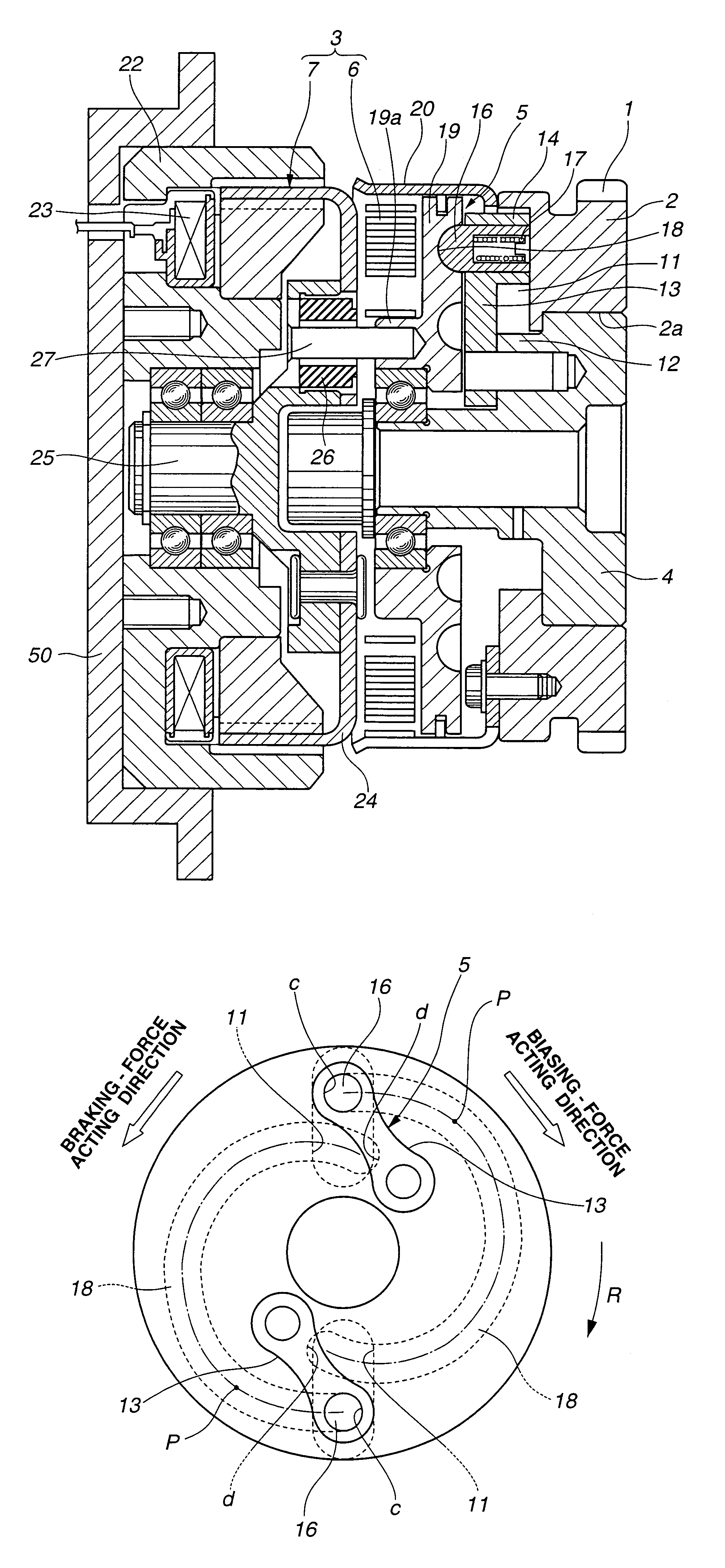
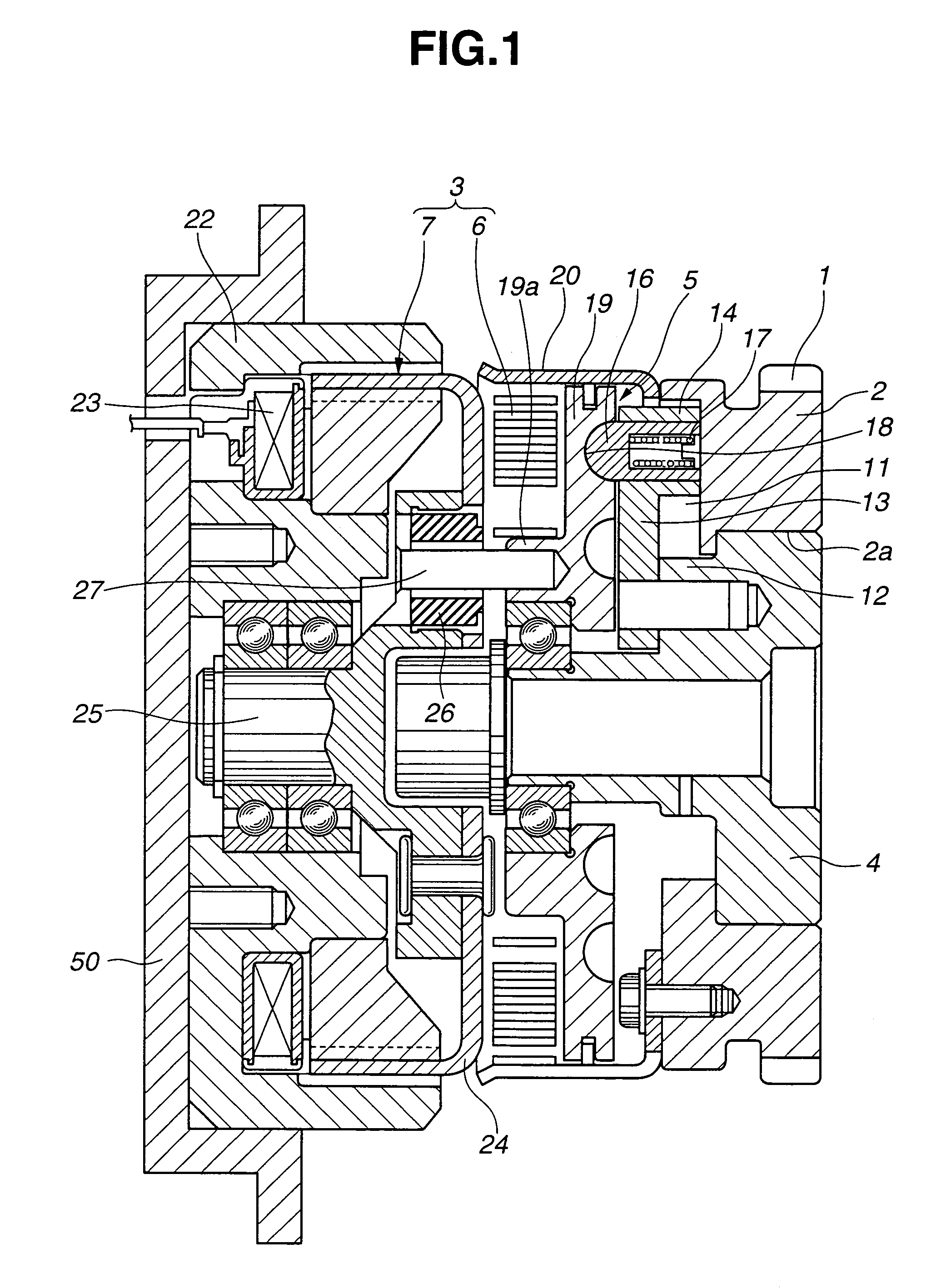
[0013]Referring to the drawings, a description will be made about a preferred embodiment of a valve timing control system for an internal combustion engine according to the present invention. In the illustrative embodiment, the present invention is applied to an intake-side valve actuating system. Optionally, the present invention can be applied to an exhaust-side valve actuating system.

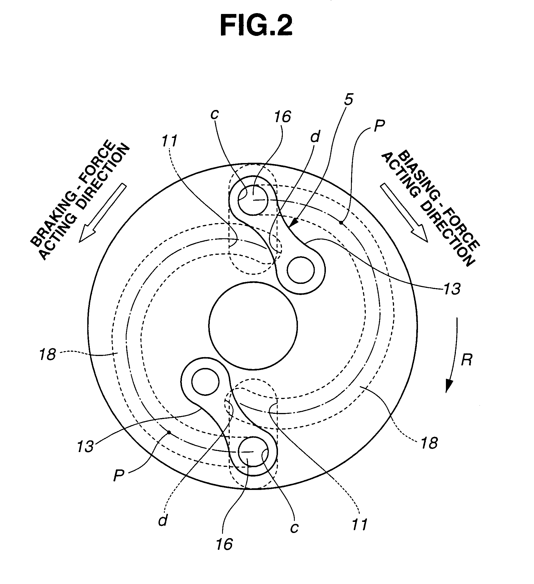
[0014]Referring to FIG. 1, the valve timing control system is disposed at a front end of a camshaft, not shown, rotatably supported on a cylinder head of the engine, and comprises a driving ring (driving rotator) 2 including at the outer periphery a timing sprocket 1 linked to a crankshaft, not shown, a driven shaft member (driven rotator) 4 integrally coupled to the front end of the camshaft and for relatively rotatably supporting driving ring 2 through the base-side outer periphery, a phase alteration mechanism 5 disposed in front of (on the left side of) driving ring 2 for operating the mounting a...


PUM


Abstract

A valve timing system for an internal combustion engine includes a phase alteration mechanism interposed between a driving rotator and a driven rotator and having a direction turning point at which the phase alteration direction is reversed when a movable portion of the mechanism travels from a beginning to a termination, and an operation control device for displacing the movable portion when undergoing an energization control, the movable portion being displaced toward the beginning when the energization control fails to be carried out. The rotation phase is set at a middle position between a maximum retard position and a maximum advance position when the movable portion is located at the beginning.

Description

BACKGROUND OF THE INVENTION[0001]The present invention relates to a valve timing control system for an internal combustion engine, which variably controls the opening / closing timing of an engine valve in accordance with the engine operating conditions.[0002]Typically, the valve timing control system comprises a housing rotated by power of a crankshaft and a camshaft-side shaft member coaxially mounted thereto, wherein the mounting angle (rotation phase) between the two can be adjusted through links and a lever. Specifically, the housing is formed with radial grooves in which respective movable guides of the links arranged at distal ends are slidably engaged. A base end of each link is rotatably coupled to the lever protrusively provided to the shaft member. An operating rotator is disposed in front of the housing and the shaft member to be rotatable relative thereto. The backside of the operating rotator is formed with a spiral groove in which the movable guides of the links are eng...

Claims


Application Information

Patent Timeline
Patent Type & Authority Patents(United States)
IPC IPC(8): F01L1/34F01L1/344F01L13/00F02D13/02
CPCF01L1/022F01L1/344F01L1/352F01L1/024F01L1/026Y10T464/30F01L2001/34483F01L2800/12F01L2820/032H02K49/104
Inventor YAMANAKA, ATSUSHI
Owner HITACHI ASTEMO LTD
Features
  • R&D
  • Intellectual Property
  • Life Sciences
  • Materials
  • Tech Scout
  • Unparalleled Data Quality
  • Higher Quality Content
  • 60% Fewer Hallucinations
Learn More