Transponder label

a transponder label and label technology, applied in the field of transponder labels, can solve the problems of unprinted surfaces on the transponder labels, problems such as protrusion of the chips, and the assembly cost, and achieve the effect of simple structur

Inactive Publication Date: 2006-12-05
ASSA ABLOY AB
View PDF22 Cites 1 Cited by
  • Summary
  • Abstract
  • Description
  • Claims
  • Application Information

AI Technical Summary

Benefits of technology

[0010]The objective of the invention is to further develop a transponder label of the general type described above in such a way that it h

Problems solved by technology

During the printing operation, for example, with a thermotransfer printer, any protrusion of the chip causes problems.
Specifically, even a very slight protrusion of the chip causes the printer head to be li

Method used


Image

  • Transponder label
  • Transponder label
  • Transponder label

Examples


Embodiment Construction

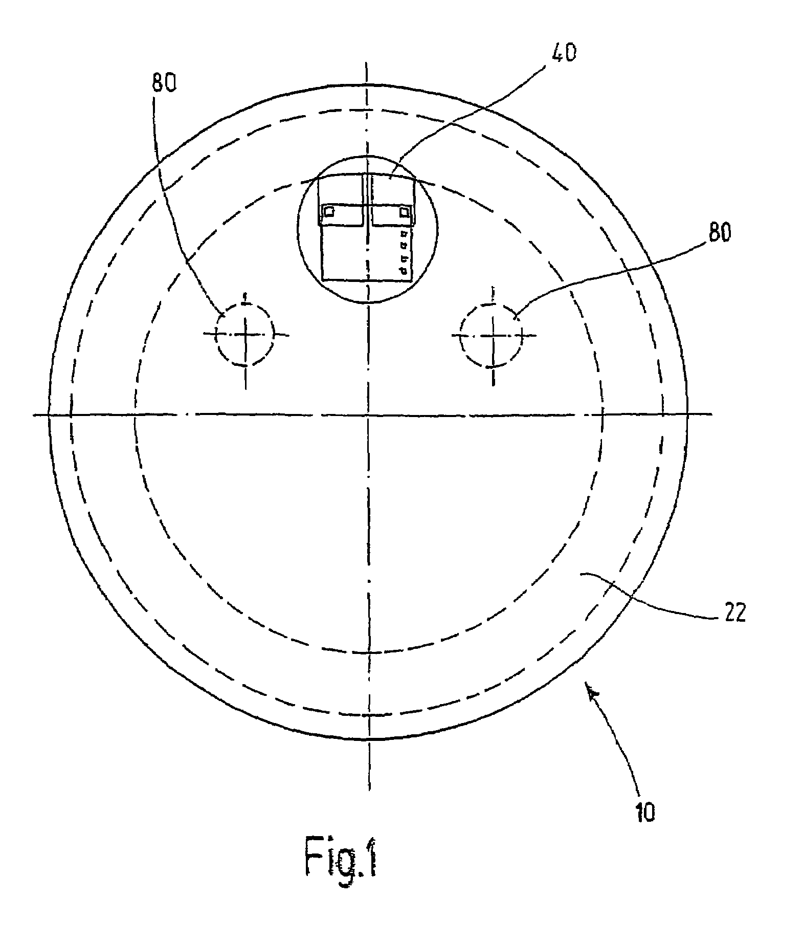
[0027]A transponder label 10 has, for example, a circular shape, as shown in FIG. 1. A chip 40 and an antenna 22 are mounted on the transponder label 10.

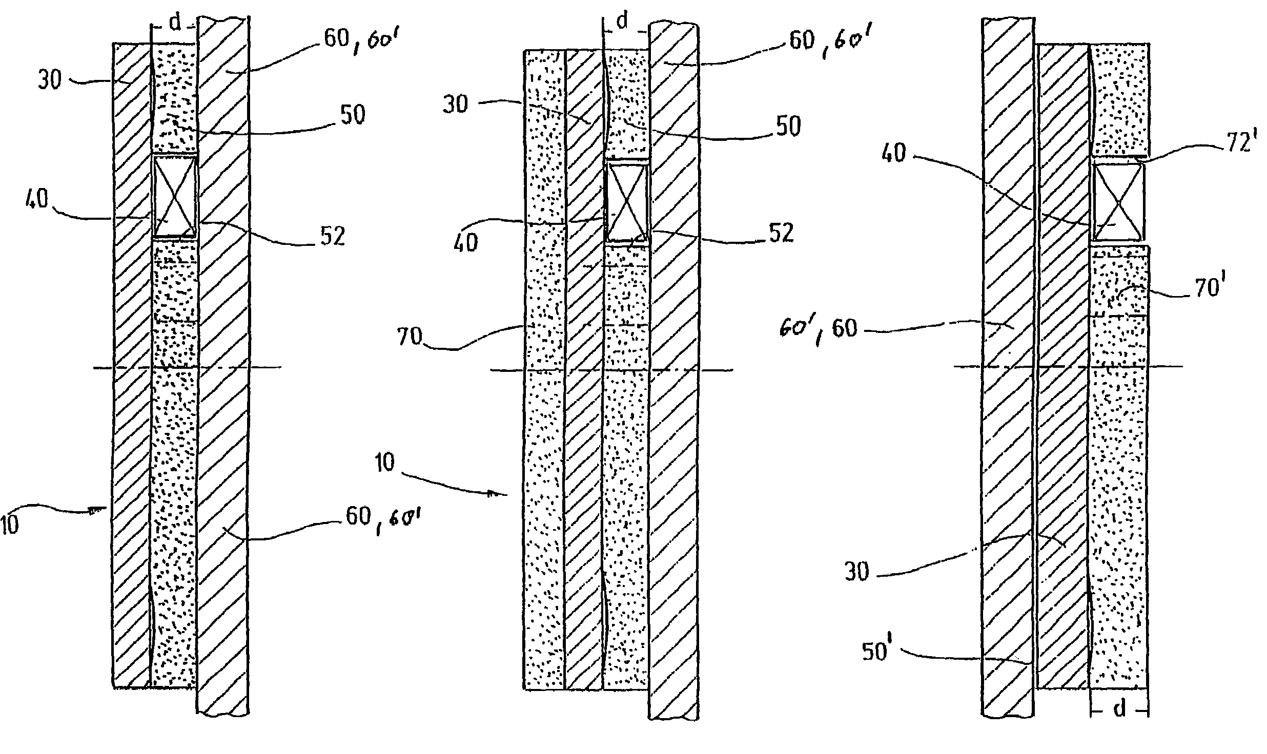
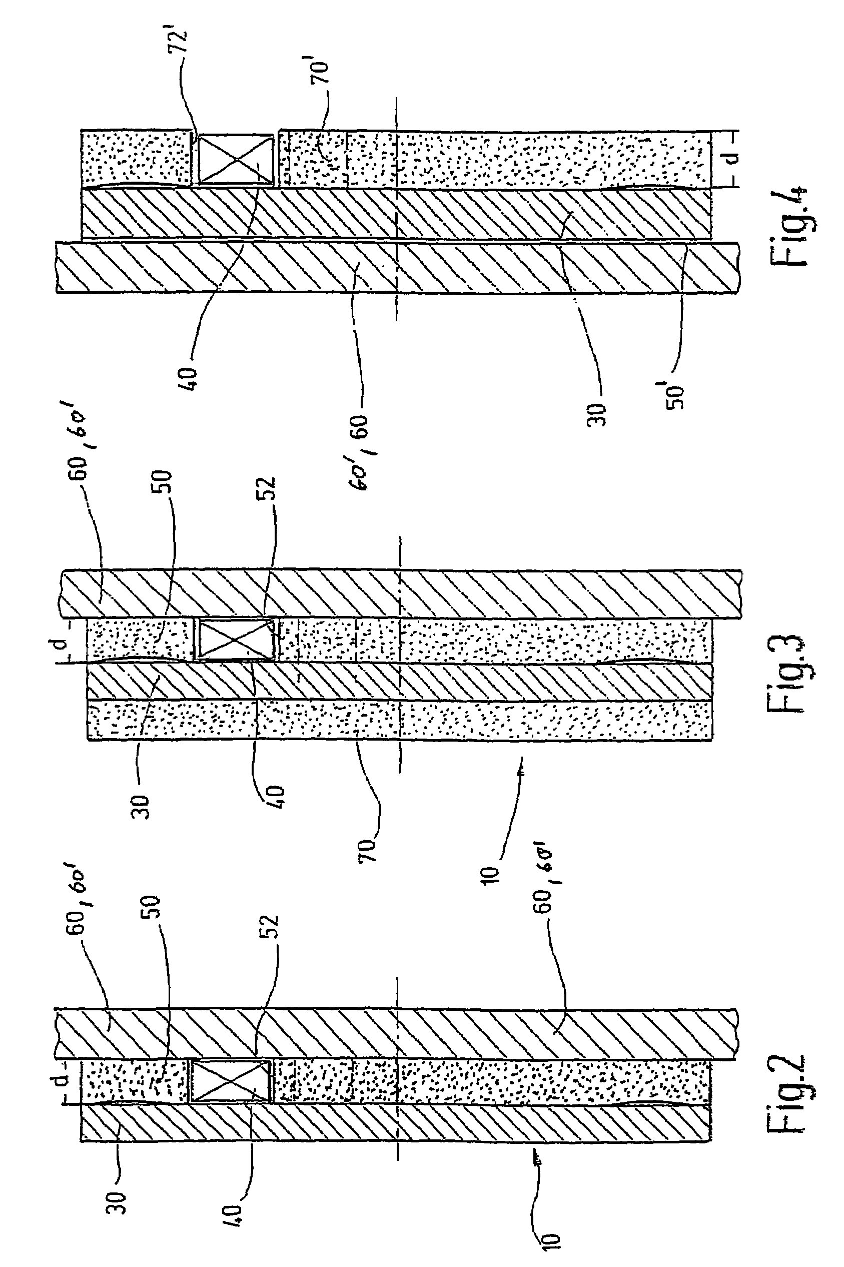
[0028]The layered structure of the transponder label 10 is shown schematically in FIG. 2.

[0029]The chip 40 is mounted on a transponder film 30 and is embedded to a certain extent in an adhesive layer 50, which can be designed, for example, as an adhesive film and has a thickness d that is at least as great as the thickness of the chip 40. In the area of the chip 40, the adhesive layer 50 has a recess 52, and it can be advantageous for the contour of the recess to match the shape of the chip 40.

[0030]The transponder film 30 can be designed as a cover film at the same time and, if necessary, can be printed on its side that faces away from the chip 40.

[0031]In another embodiment, which is illustrated in FIG. 3, elements that are identical to those of the first embodiment described above with reference to FIGS. 1 and 2 are labeled with ...


PUM


Abstract

A transponder label including a transponder film, a chip mounted on the transponder film and an adhesive layer. The adhesive layer has a thickness that is equal to the thickness of the chip. The adhesive layer also has a recess in an area of the chip, which recess has a contour that matches the shape of the chip.

Description

PRIORITY CLAIM[0001]This is a U.S. national stage of application No. PCT / IB02 / 05015, filed on Nov. 29, 2002. Priority is claimed on that application and on the following application: Country: Germany, Application No.: 201 19 356.6, Filed: Nov. 29, 2001; and[0002]Germany, Application No.: 202 08 277.6, Filed: May 27, 2002.BACKGROUND OF THE INVENTION[0003]The invention concerns a transponder label.[0004]Transponder labels are used to label objects.[0005]Transponders are passive electronic chips designed without a power supply, which are electromagnetically energized by a transponder reader and transmit stored information electromagnetically. Transponder chips have a flat design with small dimensions, which makes it possible to place them inside labels.[0006]In many cases, transponder labels are designed in such a way that they can be printed before or after they have been applied to the object to be labeled.[0007]During the printing operation, for example, with a thermotransfer printe...

Claims


Application Information

Patent Timeline
IPC IPC(8): G06K19/06G06K19/07G06K19/077
CPCG06K19/0723G06K19/07745G06K19/07749H01L2924/0002H01L2924/00
Inventor VOGT, WERNER
Owner ASSA ABLOY AB
Why Eureka
Try Eureka