
Efficient autofocus method for swath SAR

a synthetic aperture radar and efficient technology, applied in the field of autofocus methods for search (swath) synthetic aperture radar (sar) imaging, can solve the problems of image smearing in the azimuth direction, insufficient accuracy of motion compensation derived phase compensation applied to each radar a/d sample, and difficulty in estimating and correcting residual phase error for autofocus using one dimensional batch processing

Active Publication Date: 2006-12-05
RAYTHEON CO
View PDF6 Cites 17 Cited by
  • Summary
  • Abstract
  • Description
  • Claims
  • Application Information

AI Technical Summary

Benefits of technology

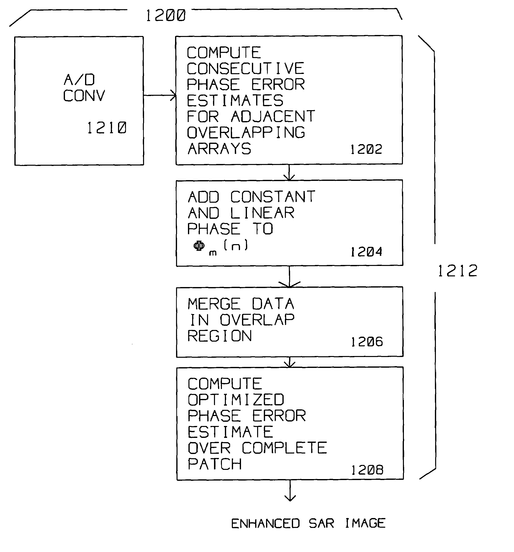
The patent describes a method for improving synthetic aperture radar (SAR) images by using multiple overlapping arrays to cover a patch and compensating for motion during the imaging process. The method involves locating strong scatterers within the radar data, motion compensating the data to obtain phase error estimates, and adding an optimizing phase to minimize the difference between the phase error estimates. The result is a more accurate and reliable image of the patch.

Problems solved by technology

For certain applications the accuracy of the motion compensation derived phase compensation applied to each radar A / D sample is insufficiently accurate.
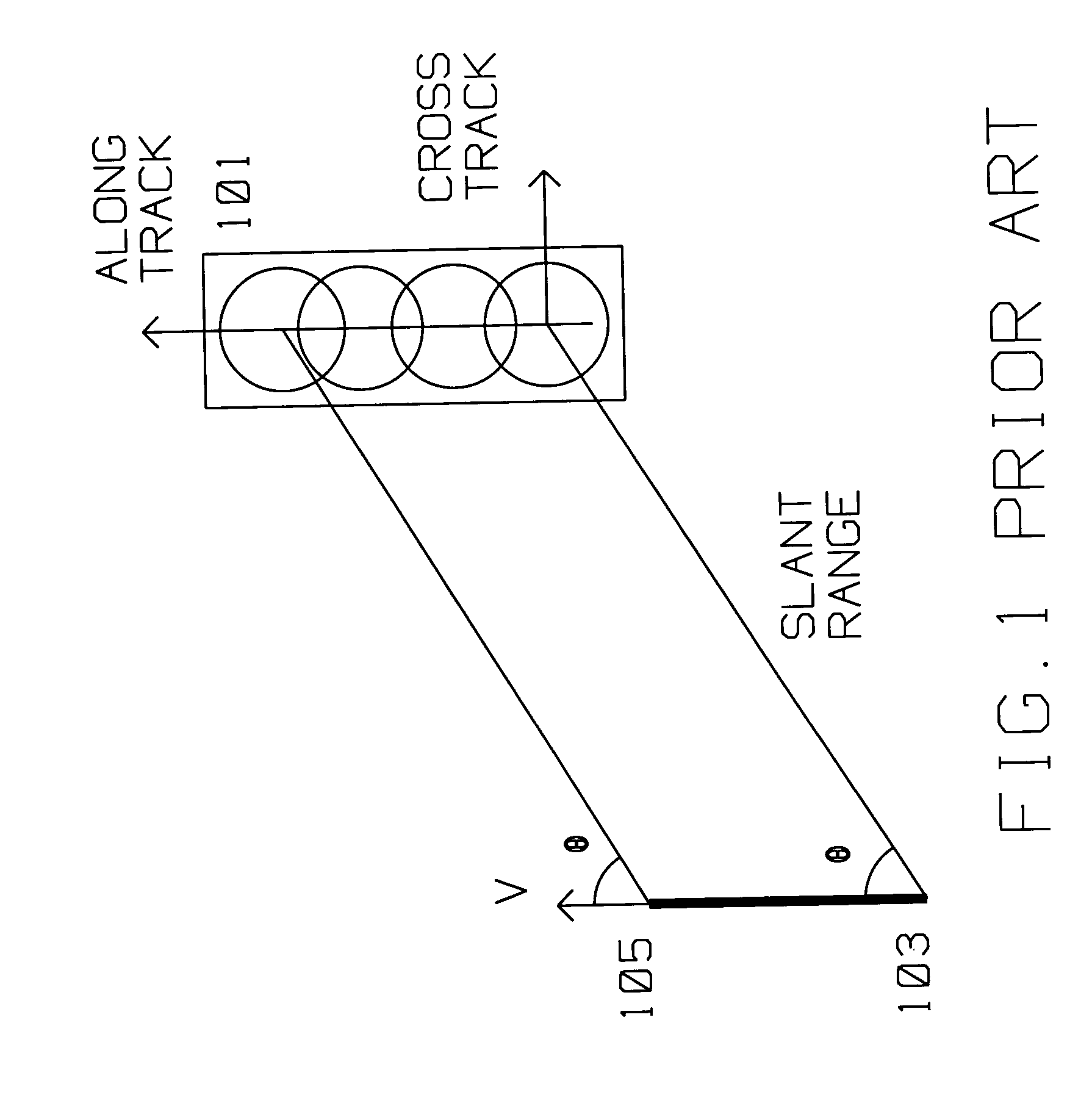
Uncompensated platform motion during search mode results in image smearing in the azimuth direction caused by pulse data that affects azimuth response.
Because target image smears in the direction of both image axes, it is difficult to estimate and correct residual phase error for autofocus using one dimensional batch processing.
Another difficulty presented during search mode is in merging the phase error for multiple parts forming the SAR image of a patch.
Hence, phase errors need to be compensated for and cannot be estimated for all ground targets in a continuous manner.
Lack of such corrections will introduce unwanted, spurious high frequency components in the resulting image thereby degrading its quality and utility.

Method used


Image

  • Efficient autofocus method for swath SAR
  • Efficient autofocus method for swath SAR
  • Efficient autofocus method for swath SAR

Examples


Embodiment Construction

[0039]The present invention describes a method for improving search type SAR images of a patch using overlapping arrays covering the patch.

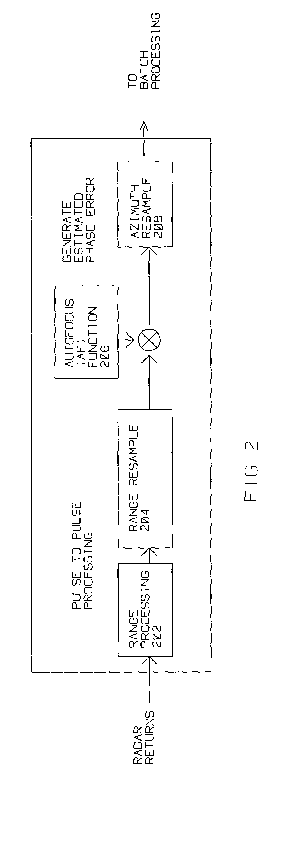
[0040]SAR images require accurate phase alignment of the reflected pulses to achieve the in-phase combination of the information contained therein. Phase errors arise from navigation data inaccuracies from motion compensation, or from atmospheric effects on radar returns causing de-focusing of SAR images. The methods used to compensate for these type of errors, is called auto-focus (AF). AF depends on information contained in motion compensated radar collected data to perform relatively fine, accurate phase correction not originally provided by motion compensation.

[0041]Unlike the case in spot SAR mode, processing for AF in search SAR mode requires continuous estimates of phase errors so multiple SAR arrays can be combined into a large patch. Furthermore, images generated in search mode are oriented in the along-track, cross track direction, unli...


PUM


Abstract

A moving radar generates a search mode synthetic aperture image of a patch from periodic pulse returns reflected from the patch. The patch is imaged from radar returns derived from two or more overlapping arrays. A strong scatterer is located within each array, then the data from each array is motion compensated with respect to the motion of the radar and the strong scatterer. The motion compensated results for each array are autofocused to derive a phase error for each array. Using the phase error for each array, a connected phase error estimate is computed, added to the phase error of each array to minimize the differences between phases in the overlap between arrays insuring that there is no or minimal phase discontinuity in the overlap region between arrays. Avoiding phase discontinuity yields a clear SAR image of the combination of arrays rendering the patch.

Description

[0001]This application is a continuation in part of U.S. Patent and Trademark Office application Ser. No. 10,996,246, titled Autofocus Method Based on Successive Parameter Adjustments for Contrast Optimization, filed Nov. 23, 2004. (ref PD-03W148).[0002]This invention was made with Government support under Contract No. F19628-00-C-0100 awarded by the Department of the Air Force. The Government has certain rights in this invention.BACKGROUND OF THE INVENTION[0003]1. Field of the Invention[0004]This invention is in the field of autofocus methods for search (swath) Synthetic Aperture Radar (SAR) imaging.[0005]2. Description of the Related Art[0006]Synthetic Aperture Radar (SAR) is used for ground mapping as well as target identification. The general principle behind SAR is to coherently combine the amplitude and phase information of radar returns from a plurality of sequentially transmitted pulses. These pulses are from a relatively small antenna on a moving platform. As the platform m...

Claims


Application Information

Patent Timeline
Patent Type & Authority Patents(United States)
IPC IPC(8): G01S13/90
CPCG01S13/90G01S13/9035G01S13/9011G01S13/904G01S13/9019
Inventor CHO, KWANG M.HUI, LEO H.
Owner RAYTHEON CO
Learn More