Socket having a structure for grasping solder balls

a solder ball and socket technology, applied in the field of sockets, can solve the problems of open solder joints, surface warpage or deformation of circuit boards, and achieve the effect of avoiding the formation of solder joints

Inactive Publication Date: 2006-12-12
TAI TWUN ENTERPRISE CO LTD
View PDF8 Cites 34 Cited by
  • Summary
  • Abstract
  • Description
  • Claims
  • Application Information

AI Technical Summary

Benefits of technology

[0015]The solder joint is formed with a protrusion adjacent to the bottom ed...

Problems solved by technology

However, this technique often results in open solder joints.
However, the surface of the circuit board 4 is not oft...

Method used


Image

  • Socket having a structure for grasping solder balls
  • Socket having a structure for grasping solder balls
  • Socket having a structure for grasping solder balls

Examples


Embodiment Construction

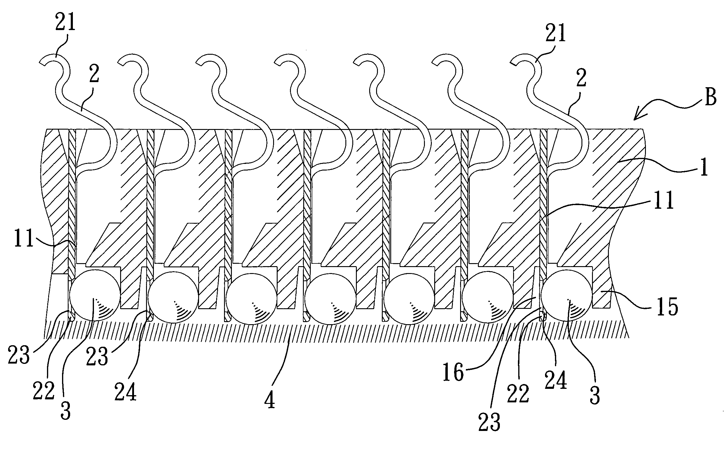
[0028]Referring to FIGS. 5˜9, FIG. 5 shows a cross-sectional view of a socket having a structure for grasping solder balls in accordance with an embodiment of the present invention. FIG. 6 is a perspective view of a part of FIG. 5 viewed from bottom. FIG. 7 is an enlarged view of a part of FIG. 5, showing a solder joint of a terminal being resiliently deformed to guide a solder ball. FIG. 8 is similar to FIG. 7 but showing the solder joint of the terminal recovering to grasp the solder ball in a grasping hole thereof. FIG. 9 is a perspective view of the terminal of FIG. 8.

[0029]As shown in FIGS. 5˜9, the socket B of the present invention includes a dielectric housing 1, a plurality of terminals 2 and a plurality of solder balls 3.

[0030]The dielectric housing 1 is defined with a plurality of terminal passages 11 in a vertical direction thereof. The terminals 2 are respectively received in the terminal passages 11. Each terminal 2 is formed with a contact portion 21 at the upper end t...


PUM


Abstract

A socket having a structure for grasping solder balls is disclosed. A grasping hole is laterally defined in the solder joint of each terminal of the socket, and a stop wall is formed at the dielectric housing spaced from the grasping hole at a proper distance. The solder ball is secured between the stop wall and the solder joint with a portion of the solder ball being received in the grasping hole. The dimension of the grasping hole is slightly larger than that of a side surface of the solder ball received in the grasping hole, whereby the solder ball is freely movable up and down in the grasping hole of the solder joint. Therefore, when the socket is soldered to the circuit board, the solder balls can automatically fully contact the surface of the circuit board.

Description

FIELD OF THE INVENTION[0001]The present invention relates to a structure for grasping solder balls, and particularly to a socket having a structure for grasping solder balls that can automatically adjust heights of the solder balls in accordance with flatness or warpage of a surface of a circuit board, whereby all the solder balls can be soldered in full contact with the surface of the circuit board.BACKGROUND OF THE INVENTION[0002]With developments of electronic circuits, digital processing bits increase in number and digital processing speed becomes faster and faster. Consequently, the number of pins of corresponding sockets must also increase. Thus, sockets having many pins have become more frequent and more important.[0003]A socket is mounted on a circuit board through surface mount technology (SMT), which often involves solder balls being disposed at a solder jointjoint of each terminal of the socket through pre-soldering or planting solder balls. However, this technique often ...

Claims


Application Information

Patent Timeline
IPC IPC(8): H01R12/00
CPCH01R12/57H01R12/7076H01R43/0256H05K3/3426H05K7/1069H05K2201/10189H05K2201/1084H05K2201/10984H05K2203/041Y02P70/50
Inventor LIN, LOUIE
Owner TAI TWUN ENTERPRISE CO LTD
Why Eureka
Try Eureka