

Roof lining of a vehicle and a method for producing same
- Summary
- Abstract
- Description
- Claims
- Application Information
AI Technical Summary
Benefits of technology
Problems solved by technology
Method used
Image

Examples
Embodiment Construction
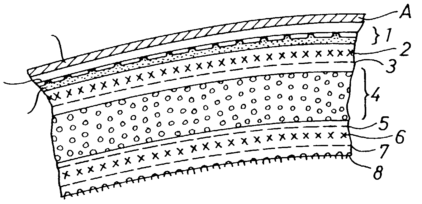
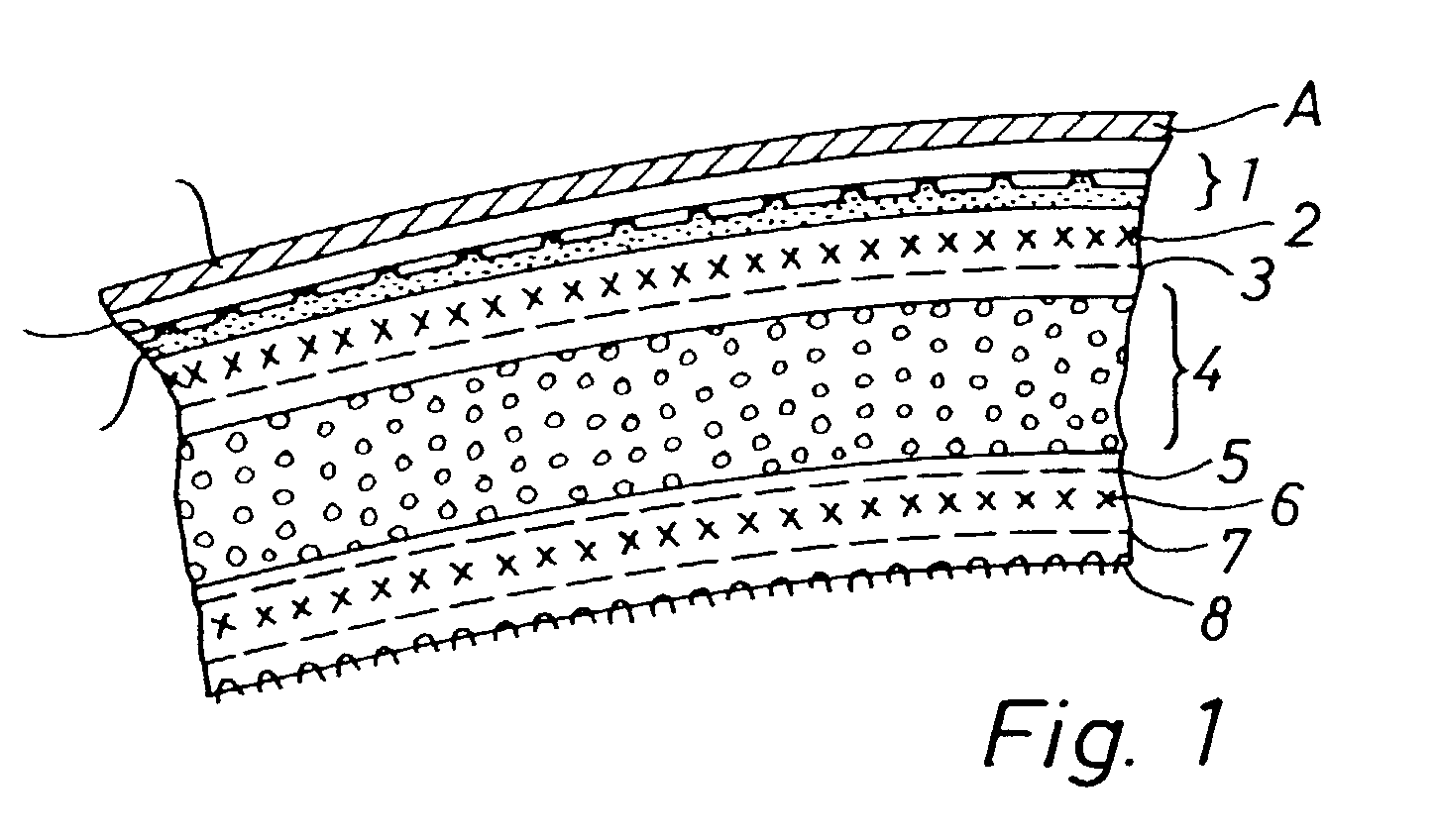
[0027]The embodiment described above can easily be acoustically trimmed by the expert without negatively influencing its advantageous effects. In particular, the thickness of the core layer 4 can be adjusted to meet the requirements, i.e. to have a weight of less than 0.2 kg / M2 up to a weight of more than 0.4 kg / M2. The décor layer 8 can comprise imaginative textiles or layers having foram backing. The layers 5, 6, 7, 8 on the passenger compartment side can be formed such that their air flow resistance meets the desired acoustic requirements. By varying the stiffening layer 2 on the metal roofing sheet side the stiffness of the entire lining can be adjusted as desired. A variation in the composition of the stiffening layers 2 and 6 is also within the skill of the expert. Also any specific shaping of the roof lining and in particular a specific surface pattern on the rear side of the lining can be freely chosen.
[0028]The inventive method for manufacturing such a roof lining has the f...
PUM
| Property | Measurement | Unit |
|---|---|---|
| Thickness | aaaaa | aaaaa |
| Thickness | aaaaa | aaaaa |
| Thickness | aaaaa | aaaaa |
Abstract
Description
Claims
Application Information