Zero insertion force contact and socket connector having the contact

Inactive Publication Date: 2011-02-10
HON HAI PRECISION IND CO LTD
View PDF8 Cites 5 Cited by
  • Summary
  • Abstract
  • Description
  • Claims
  • Application Information

AI Technical Summary

Benefits of technology

Accordingly, an object of the present invention is to provide a conta

Problems solved by technology

The contact has such a complicated structure

Method used


Image

  • Zero insertion force contact and socket connector having the contact
  • Zero insertion force contact and socket connector having the contact
  • Zero insertion force contact and socket connector having the contact

Examples


Example

Reference will now be made in detail to the preferred embodiment of the present invention.

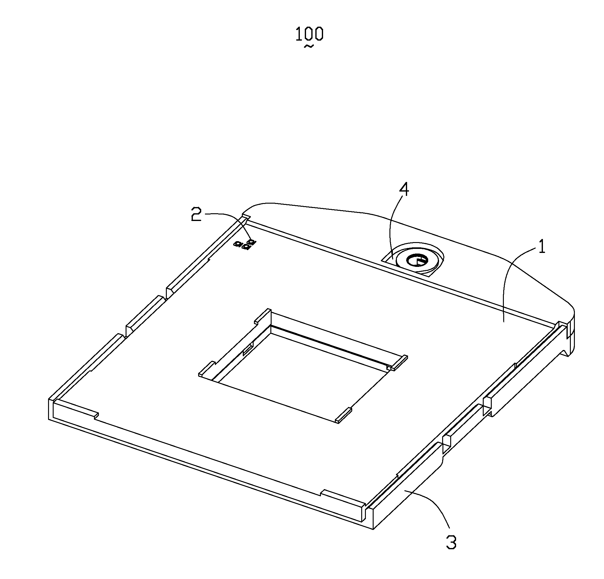
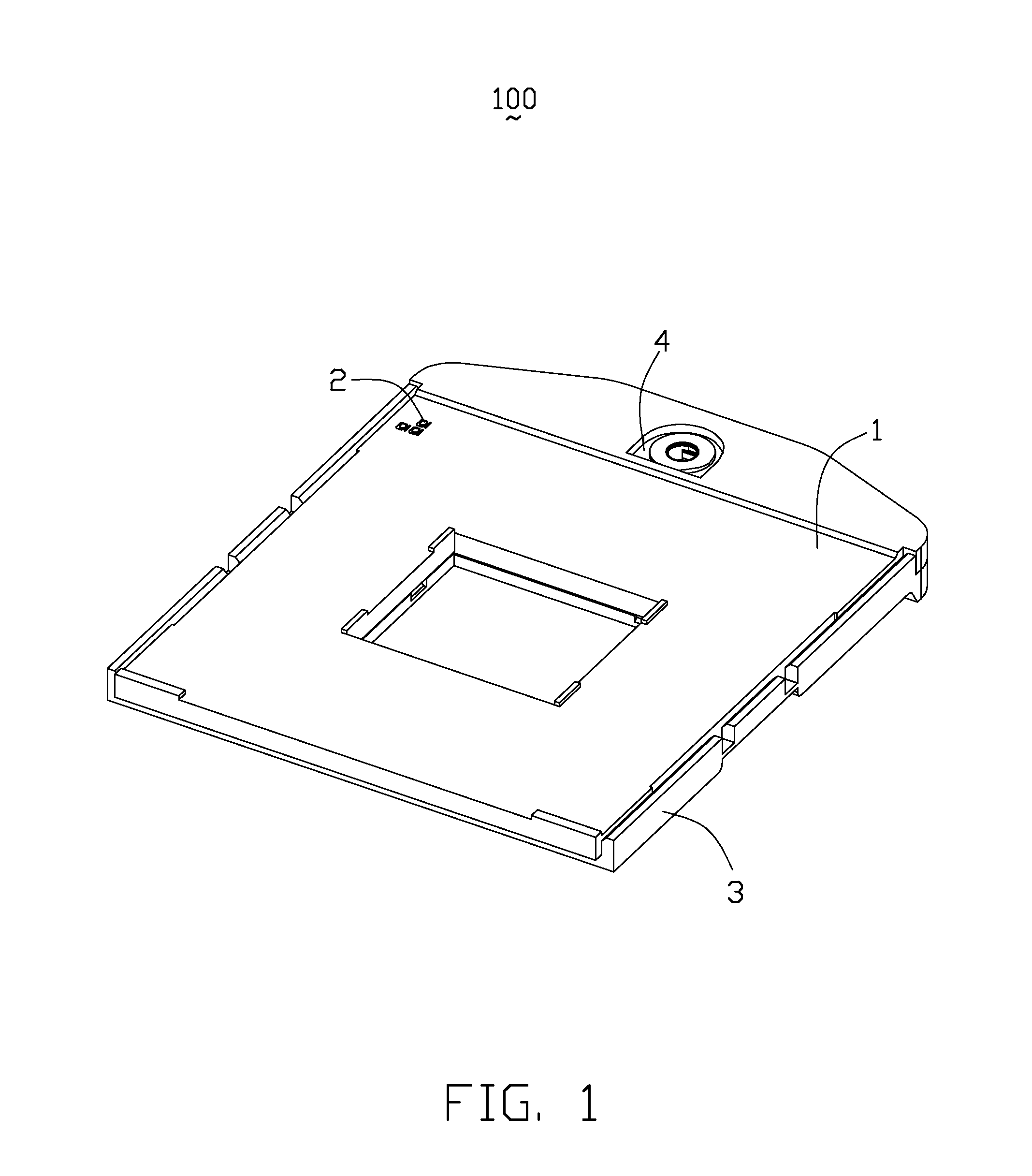
Referring to FIGS. 1-3, a socket connector 100 of the present invention, used for connecting with a CPU (Central Processing Unit, not shown), comprises a base 3, a plurality of contacts 2 received in the base 3, an insulative cover 1 attached onto the base 3 and moveable between an open position at which the contacts 2 disconnect with pins of the CPU and a closed position at which the contacts 2 electrically connect with the pins of the CPU, and an actuating element 4 of known design suitable for causing the movement of the insulative cover 1 relative to the base 3 in a condition that a user rotates the actuating element 4 by a tool (not shown).

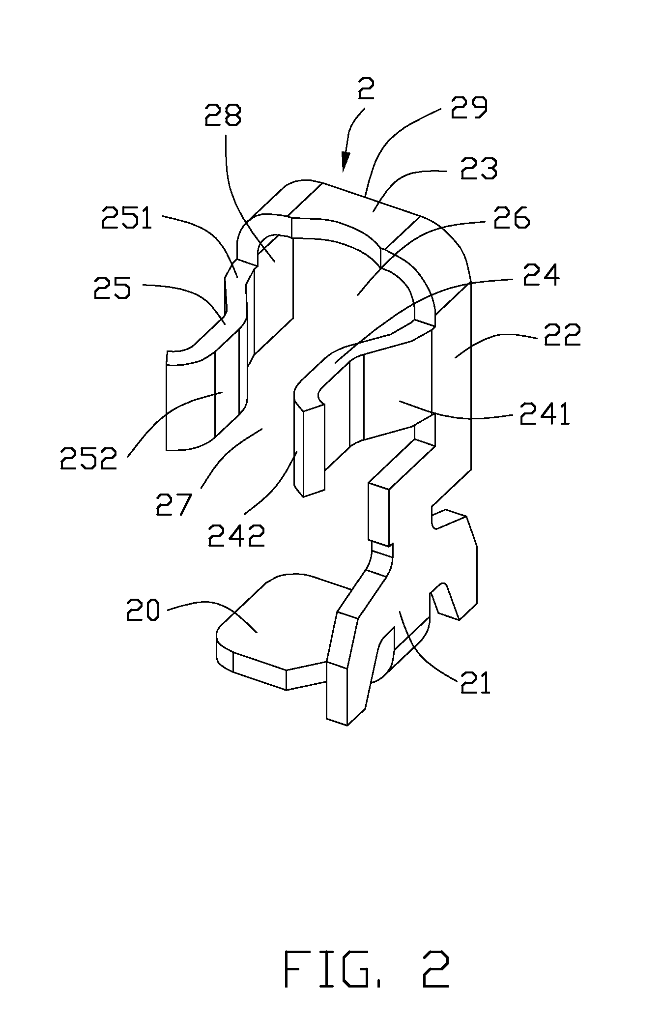
Referring to FIGS. 2 and 3, the contact 2 comprises a fixed portion 21, a soldering portion 20 bending laterally from a lower end of the fixed portion 21, an inversed U-shaped extension portion 29 extending from an upper end of the fixed portion 21 and f...


PUM


Abstract

A contact (2) includes a fixed portion (21) in a first, vertical direction, a soldering portion (20) bending from a lower end of the fixed portion and extending in a second, horizontal direction, and an inversed U-shaped extension portion (29) extending from an upper end of the fixed portion and facing to the soldering portion. The extension portion has a pair of spaced arm portions (22, 28) and a connecting portion (23) connecting with the spaced arm portions. The contact further includes a first elastic portion (24) connecting to one of the arm portions and a second elastic portion (25) connecting to the other one of the arm portions. The first elastic portion and the second elastic portion laterally extend from a same side of the extension portion and extend in a third direction perpendicular to the vertical direction and the horizontal direction.

Description

BACKGROUND OF THE INVENTION1. Field of the InventionThe present invention relates generally to a ZIF (Zero Insertion Force) contact and a socket connector having the ZIF contact, and more particularly to ZIF contacts with small arrangement distance therebetween before being cut from a terminal material belt and the socket connector having the ZIF contacts.2. Description of Related ArtsTW Pat. No. M336581 issued to Molex on Jul. 11, 2008 discloses a terminal and an electrical connector which is provided with the terminal. The terminal includes a fixing part, a first elastic arm and a second elastic arm, two contact parts, two guide parts and a welding part. The fixing part is provided with a front panel and a top end part. The first elastic arm, the second elastic arm and the fixing part are punched on the same panel to lead the first elastic arm and the second elastic arm to respectively, parallelly extend upwards from the top end part of the fixing part. The contact parts extend re...

Claims


Application Information

Patent Timeline
IPC IPC(8): H01R13/62H01R4/02H01R24/00
CPCH01R12/57H01R13/11H01R12/727H01R43/16H01R13/193H05K7/1084
Inventor YEH, CHENG-CHI
Owner HON HAI PRECISION IND CO LTD
Why Eureka
Try Eureka