In many industries, operations must be performed on structures, such as multiple layer structures, and problems arise if the multiple
layers of the structure cannot be securely held together during the operation.
Thus, if burrs, debris and / or excessive
sealant are present, then the
layers cannot be properly fastened, and the layers may suffer
corrosion,
cracking and / or premature fatigue failure, which generally renders the structure ineffective for its intended purpose and, therefore, subject to the expense of repair or replacement.
In the
aerospace industry, for example, a significant amount of time and labor is expended ensuring that the holes through the various layers of the aircraft structure are appropriately drilled, cleaned, sealed and fastened.
This can cause a gap to develop between a drilled layer and the next layer, particularly when the layers are a stack-up of thin material.
The gap between the layers causes burrs about the hole and debris is likely to gather between the layers.
Thus, once the holes are drilled, the layers must be disassembled, the burrs must be removed from the holes, and the debris must be cleaned from the surfaces of the layers, all of which is a time-consuming and labor intensive process.
Overall, this process is expensive, laborious, and time-consuming.
In addition, the integrity of the resulting holes depends upon the completion of many manual processes, which creates a risk that certain steps may be performed inadequately or completely overlooked.
For complex structures and structures that are not easily accessible, it is difficult if not impossible to utilize a clamp.
In addition, bulkheads, fittings and the like in the structure also interfere with the use of a clamp on the structure.
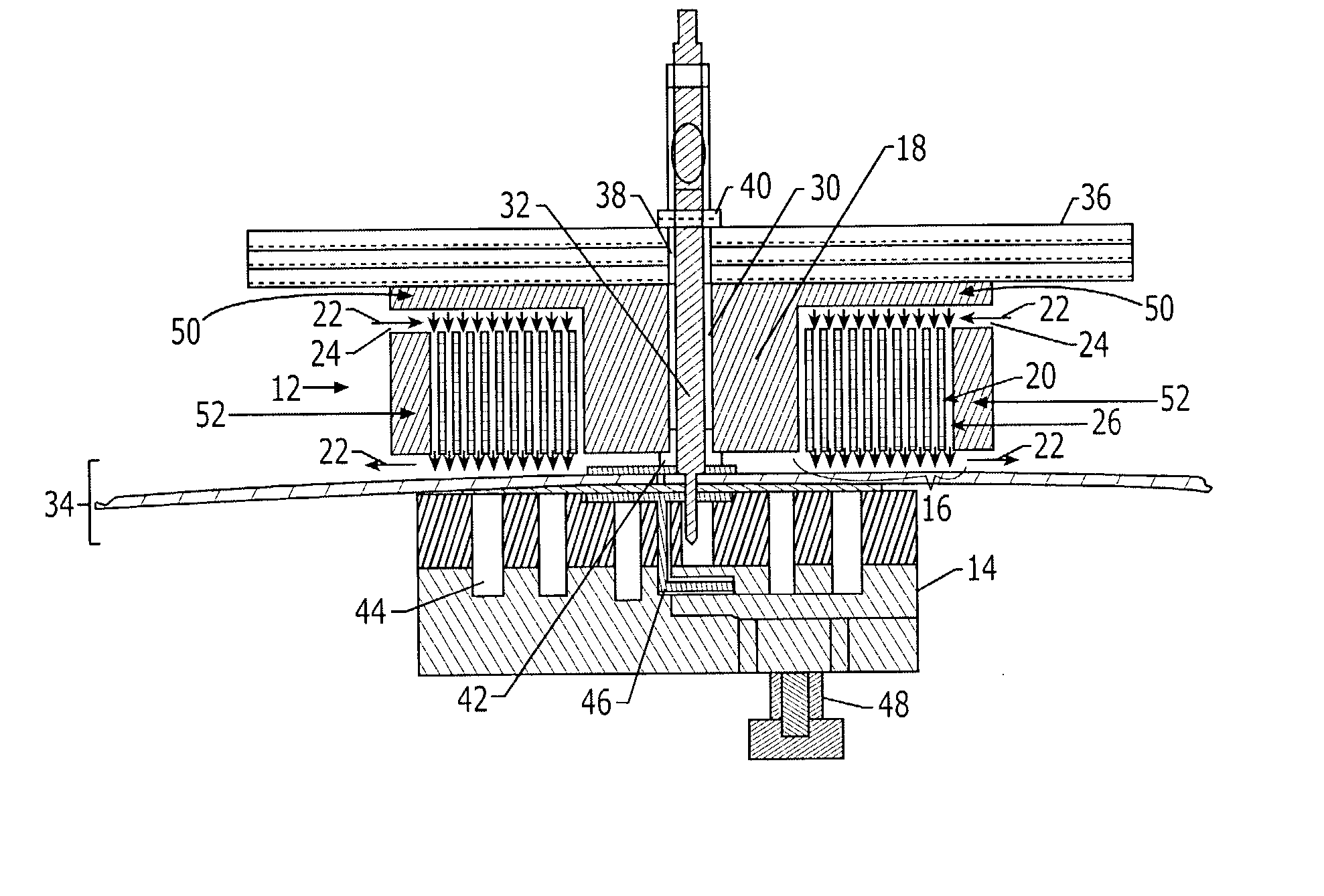
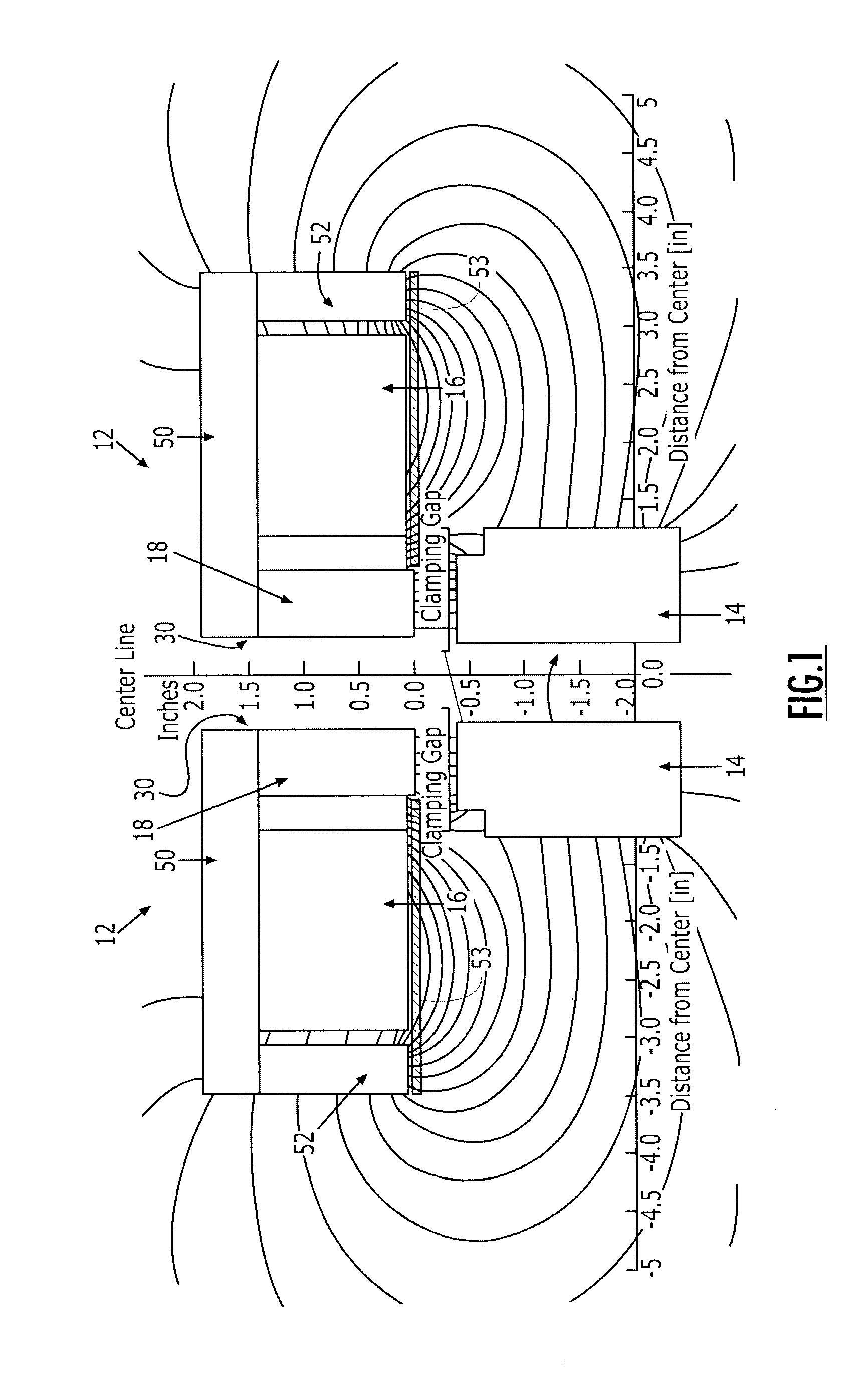
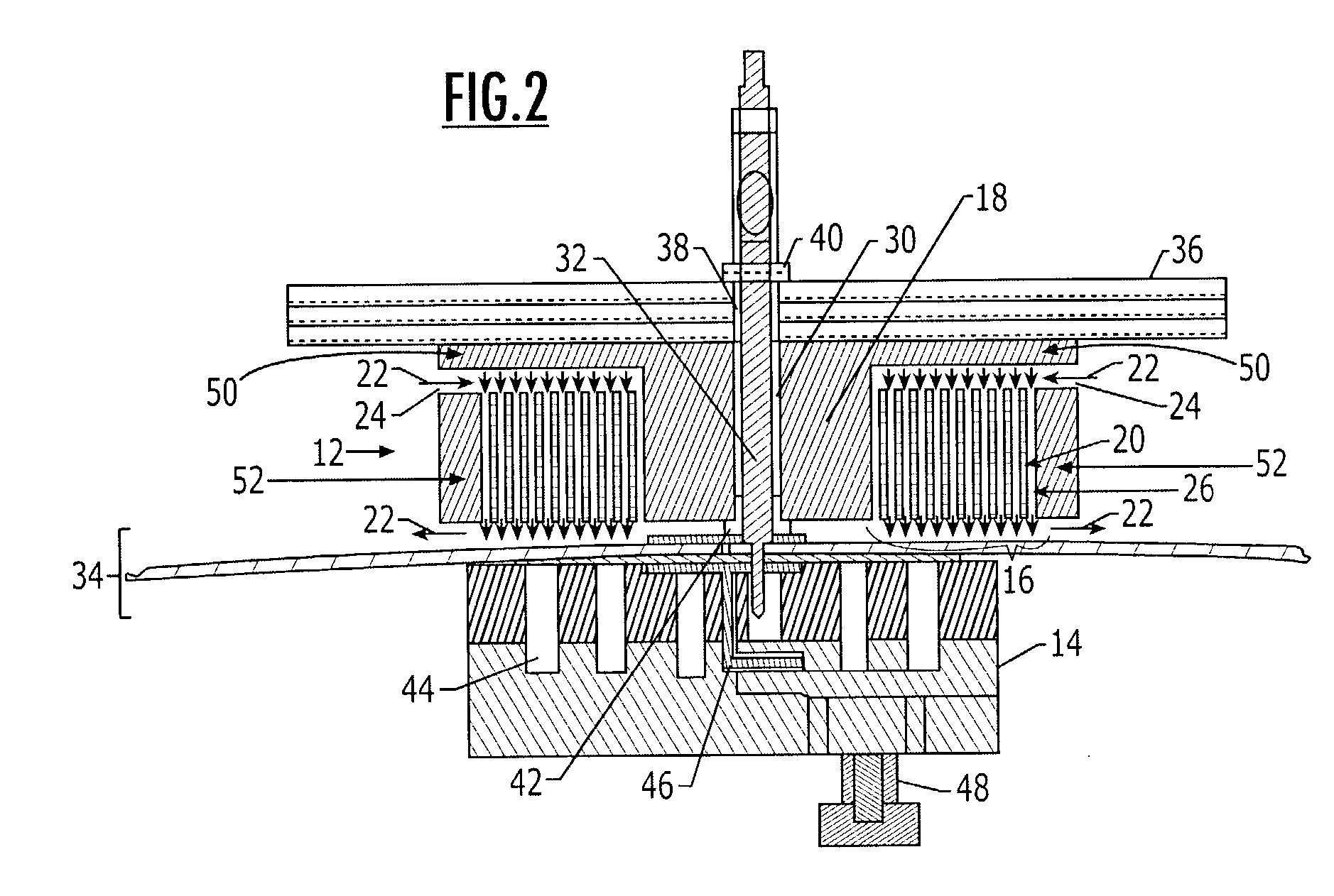
If any gap exists between a conventional electromagnet and the
ferrous material, however, significant losses in the force between the electromagnet and the
ferrous material result.
Conventional electromagnets, therefore, do not create enough force to securely clamp multiple layers of a structure together because the force between a conventional electromagnet and the piece of
ferrous material is subject to the inverse square law, i.e., the force is proportional to the inverse square of the distance between the electromagnet and the piece of ferrous material.
If a 1 / 16-inch gap of air or any non-ferrous material is introduced between the electromagnet and the ferrous material, the force between the electromagnet and the ferrous material drops to 95 lbs., which is not a sufficient amount of force to securely clamp a multiple layer structure together.
Since the structures are often formed of a non-ferrous material, however, this marked decrease in the clamping force due to the gap created by the structure poses a significant limitation upon the use of electromagnets for clamping any type of structure, including multiple layer structures.

