Multi-band antenna

a multi-band antenna and antenna technology, applied in the field of antennas, can solve the problems of reducing operation reliability, increasing the complexity of the radio frequency system (rf system), and ordinary antennas are always bothered by multi-path interference problems, and achieve excellent high frequency characteristics and electromagnetic compatibility

Active Publication Date: 2006-12-12
QUANTA COMPUTER INC
View PDF8 Cites 235 Cited by
  • Summary
  • Abstract
  • Description
  • Claims
  • Application Information

AI Technical Summary

Benefits of technology

[0008]It is therefore an object of the invention to provide a multi-band antenna, which uses a single antenna body manufactured into a unity to produce multi-band operating characteristics and when combined with a shielding metal provides the system with excellent high frequency characteristics and electromagnetic compatibility even when disposed in a small space.
[0010]The multi-band antenna includes a radiating element, a grounding plane, a short-circuiting element and a short-circuiting regulator. The radiating element has a feed-in point for transmitting signals and several radiation arms. Of which, the first radiation arm and the second radiation arm respectively have a first resonant mode and a second resonant mode which jointly generate a high frequency operating band, while the third radiation arm has a third resonant mode which generate a low frequency operating band. The grounding plane is connected to the radiating element via the short-circuiting element to miniaturize the scale of the antenna. The short-circuiting regulator of the grounding plane improves the impedance when high frequency resonance occurs. In practical application, a coaxial line can be used to transmit the signals, of which, the core wire of the coaxial line is coupled to the radiating element at the feed-in point while the outer conductor of the coaxial line is coupled to the grounding point of the grounding plane.

Problems solved by technology

When in service, ordinary antennae are always bothered by multi-path interference problem.
Obviously, such a design will largely increase the complexity of the radio frequency system (RF system), reduce operation reliability, and increase manufacturing costs.
However, such a design has inherent restrictions, i.e., a multiple relationship exists among the central frequency of each resonant mode and that all of the frequency bands are narrow whose bandwidth is hard to expand.
Consequently, the transmission efficiency of electromagnetic waves in high frequency range is normally poor, affecting signal quality greatly.
Furthermore, the overall bandwidth, which is near 1 GHz, is too wide.

Method used


Image

  • Multi-band antenna
  • Multi-band antenna
  • Multi-band antenna

Examples


Embodiment Construction

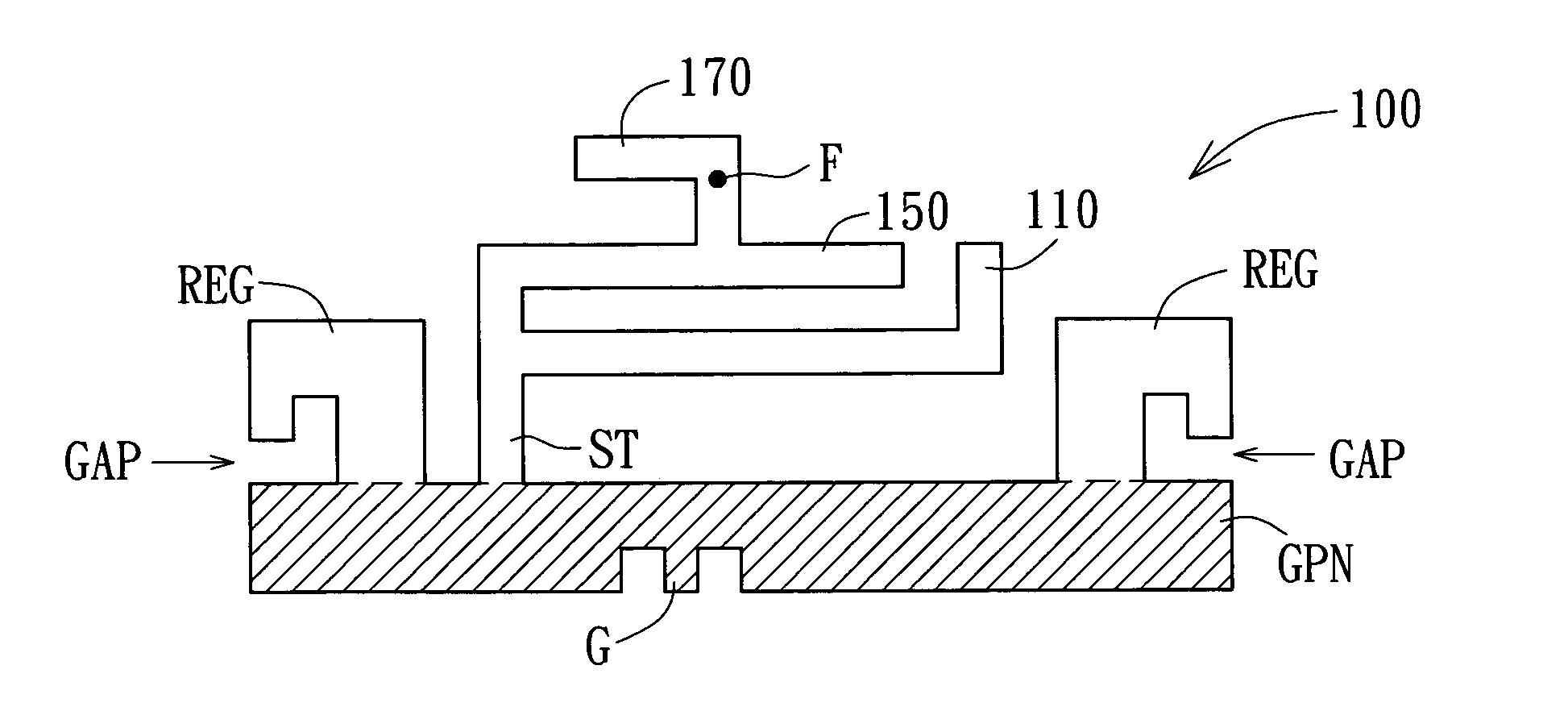
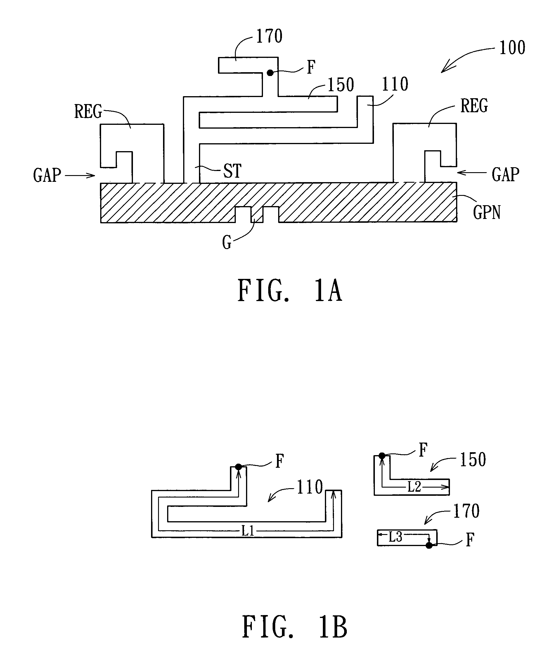
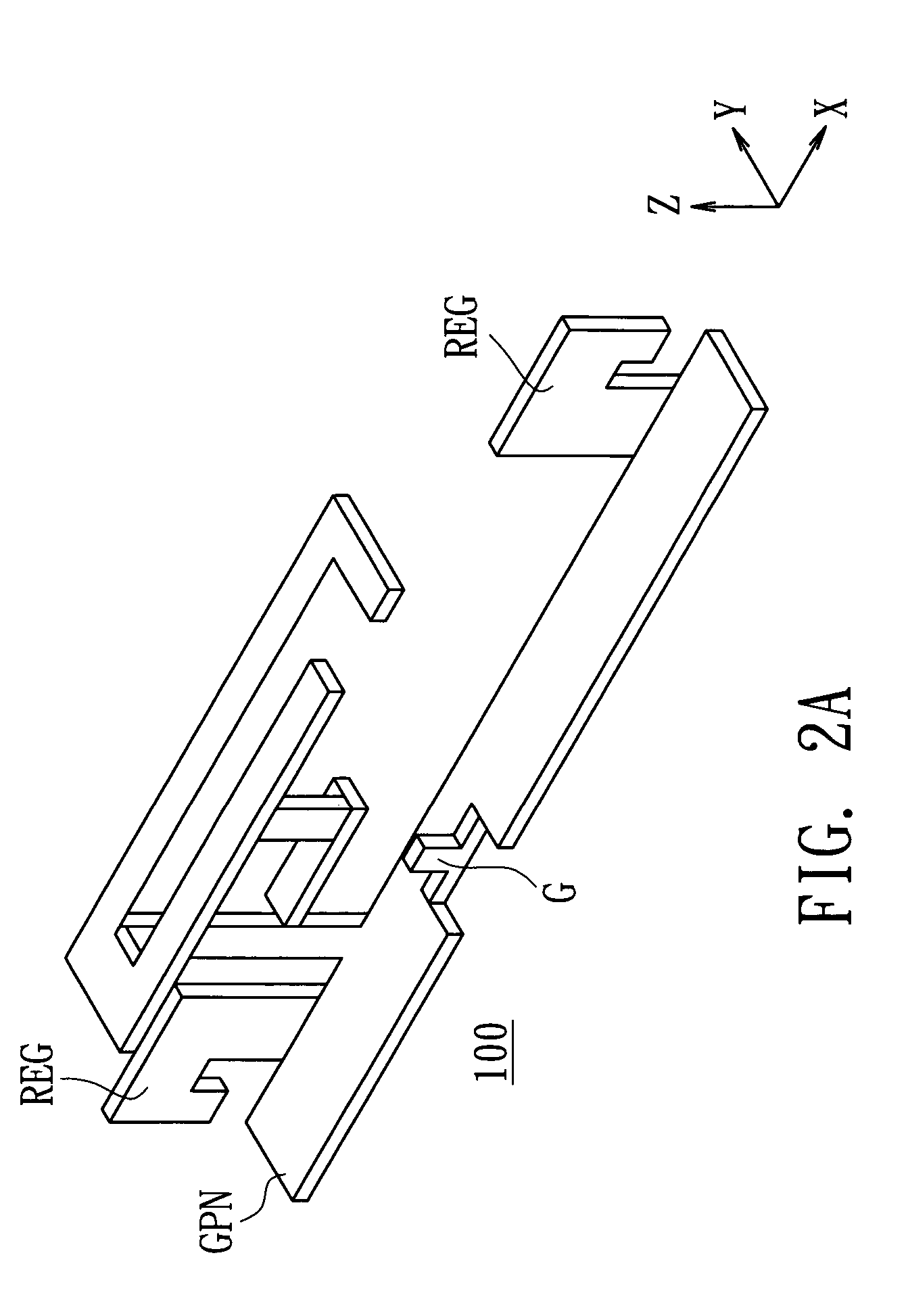
[0019]Referring to FIG. 1A, a schematic diagram of a multi-band antenna according to a preferred embodiment of the invention is shown. Multi-band antenna 100 whose antenna body is manufactured into a unity includes a radiating element, a grounding plane GPN, a short-circuiting element ST and a short-circuiting regulator REG. The radiating element, which includes radiation arms 110, 150 and 170, enables the multi-band antenna 100 to have multi-band operating characteristics. As for how the multi-band antenna 100 meets the operating bandwidth requirement for the operation of the 2.4 GHz frequency band and the 5 GHz frequency band in the application of WLAN 802.11a / b and WLAN 802.11a / g is described below. For convenience, the frequency range of 2.4˜2.4835 GHz is defined as low frequency operating band while the frequency range of 5.15˜5.825 GHz is defined as high frequency operating band to meet the requirement in the design of multi-band operation.

[0020]With regard to signal transmiss...


PUM


Abstract

A multi-band antenna having a low frequency operating band and a high frequency operating band is provided. The multi-band antenna includes a radiating element, a grounding plane, a short-circuiting element and a short-circuiting regulator. The radiating element has a feed-in point for transmitting signals and several radiation arms. The first and the second radiation arms respectively have a first resonant mode and a second resonant mode which jointly generate a high frequency operating band, while the third radiation arm has a third resonant mode which generates a low frequency operating band. The grounding plane is connected to the radiating element via the short-circuiting element to miniaturize the scale of the antenna. The short-circuiting regulator of the grounding plane enhances the impedance matching when high frequency resonance occurs.

Description

[0001]This application claims the benefit of Taiwan application Serial No. 92136635, filed Dec. 23, 2003, the subject matter of which is incorporated herein by reference.BACKGROUND OF THE INVENTION[0002]1. Field of the Invention[0003]The invention relates in general to an antenna, and more particularly to a multi-band antenna.[0004]2. Description of the Related Art[0005]In wireless communication system, antenna serves as a medium for the transmission and reception of electromagnetic signals, and the electrical characteristics of an antenna influence the quality of telecommunication. When in service, ordinary antennae are always bothered by multi-path interference problem. To solve this problem, one of the solutions is to improve the quality and performance of signal transmission / reception by means of antenna diversity structure. When the system is operating under a single frequency band, the user may use two or more sets of single band antenna to form an antenna diversity system. Fo...

Claims


Application Information

Patent Timeline
Patent Type & Authority Patents(United States)
IPC IPC(8): H01Q1/38H01Q1/24H01Q5/00H01Q5/371H01Q5/385H01Q9/04H01Q19/00
CPCH01Q1/243H01Q9/0421H01Q5/385H01Q5/371H01Q19/005
Inventor LIN, HUEI
Owner QUANTA COMPUTER INC
Why Eureka
Try Eureka