Light-weight self-propelled vacuum cleaner

Active Publication Date: 2006-12-19
TACONY A MISSOURI
View PDF13 Cites 98 Cited by
  • Summary
  • Abstract
  • Description
  • Claims
  • Application Information

AI Technical Summary

Benefits of technology

[0003]The vacuum cleaner design disclosed hear teaches a way to provide a self-propelled vacuum cleaner with little or no added weight to the vacuum. Traditionally, putting a wheel drive system on a vacuum cleaner has greatly increased the weight of the vacuum. The need for a heavy transmission, clutch and large drive wheels has made power assisted or self-propelled vacuums bulky. The disclosed invention provides very precise motion control without the need for drive wheels, control switches, clutches, or a bulky transmission. Instead, the disclosed invention relies on rotary brush agitator friction (traction) to self-propel the vacuum. Most vacuums use a single rotary brush agitator, sometimes referred to as a “beater-bar”, to agitate a carpeted surface to loosen dirt. The vacuum power head disclosed here requires at least two rotary agitators. On the disclosed designs the agitators rotate in opposite directions so that dirt may be swept into the area between them by the brushing action of the agitators. This dual agitator action is organized so that pulling and pushing on the vacuums handle causes one or the other rotary agitator to have greater traction than the other and thus create a net propelling force on the vacuum's power head. When the handle is pushed forward, more force is placed on the front roller and thus causes it to provide greater frictional contact. The difference between the friction force on the two rotary agitators determines the net force generated. Since the bottom of the front agitator rotates from front-to-back, greater contact force on this agitator causes a force to be generat

Problems solved by technology

Many rug shampooers exist that use counter rotating brushes to cancel the forces generated by the scrubbing, and provide self-propelled function without lifting and lowering their handle, which provides a self-propelled assisted action similar to the Applicants, but are not designed to work in the environment of a vacuum cleaner where faster moving rotary agitators are

Method used


Image

  • Light-weight self-propelled vacuum cleaner
  • Light-weight self-propelled vacuum cleaner
  • Light-weight self-propelled vacuum cleaner

Examples


Example

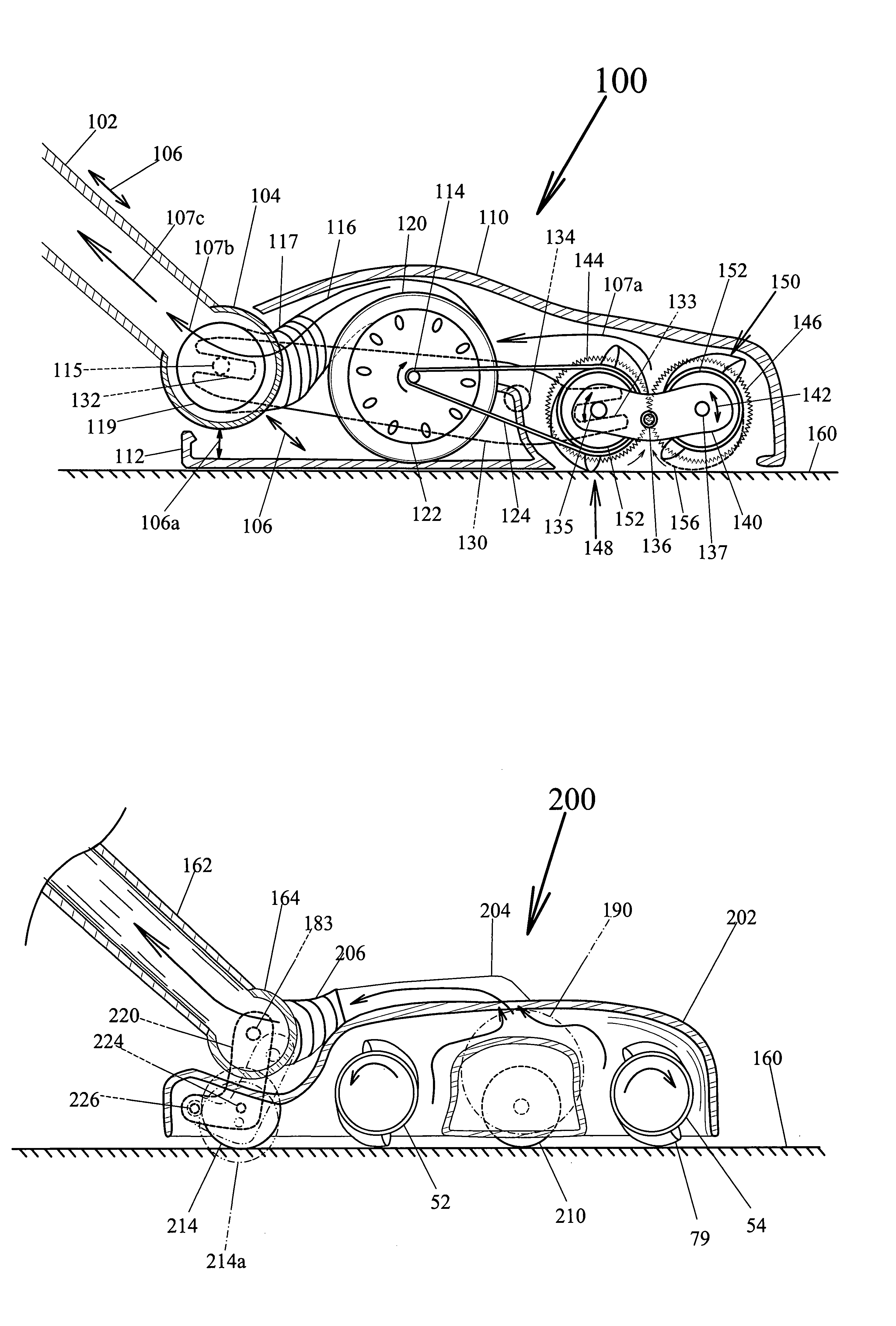
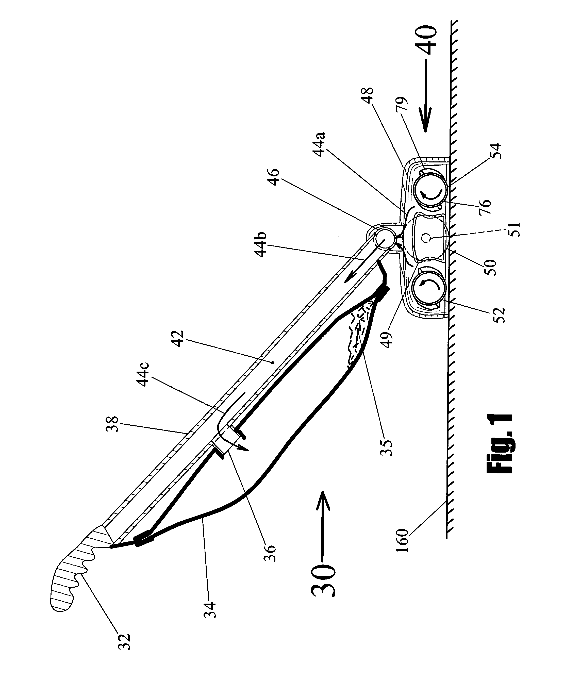
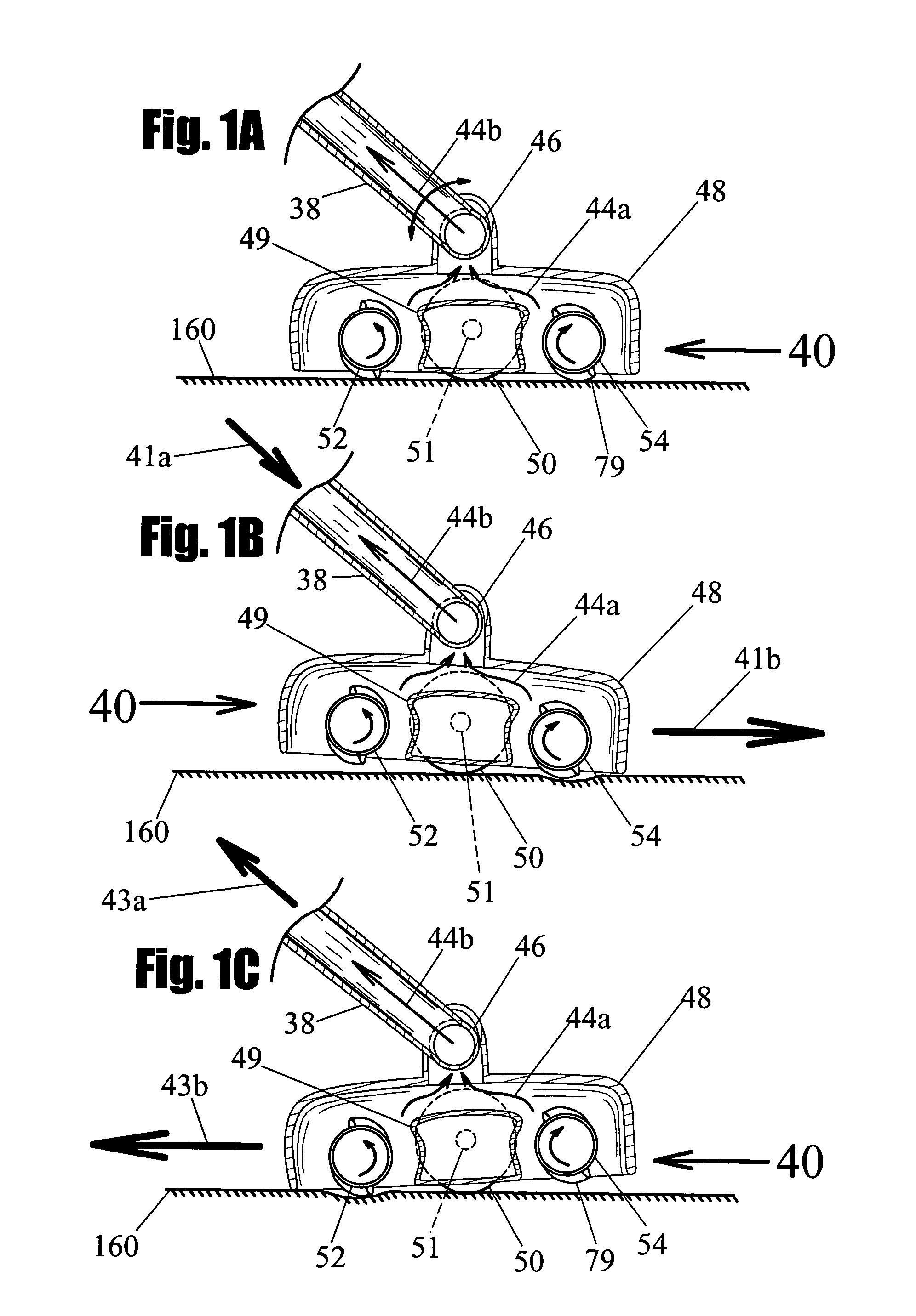
[0021]The use of vacuum cleaners for cleaning floors is well known. Vacuums are made in many different styles and types. A basic vacuum design includes a handle portion (which normally includes a dirt collection bag), and a vacuum power head. The power head generally comprises a rotary agitator, an agitator motor, and a pivoting attachment to the handle portion. This pivoting attachment sometimes includes an air conduit for passing dust from the power head to the collection bag. All the designs show here, show the air conduit built into the handle, however, a separate air conduit may easily be used to connect the collection bag and the power head. This would eliminate the need for the air conduit to pass through the handle pivot joint. The suction motor and suction fan that provide the airflow to transfer dust to the bag can be mounted in the handle portion or in the power head portion depending on the style of vacuum it is, or external to both the handle portion and power head, as ...


PUM


Abstract

A vacuum cleaner power head (40) for vacuum cleaning and having two counter rotating agitators 52 and 54. Motor (60) rotates agitators (52) and (54) through transmission (70), and also rotates suction fan (65) to provide suction air to the rotary brush agitators. Exterior housing 48 and inner housing (49) provide air suction passageways to direct suction air through fan (65) and out of the housing to a dirt collection bag (34). Self-propelled function is provided by using user force on handle (32) to create differential contact friction between the two counter-rotating rotary brush agitators so that a net traction force is generated that propels power head (40) in the direction the user is pushing.

Description

CROSS-REFERENCE TO RELATED DOCUMENTS[0001]This patent application claims priority from U.S. Provisional application Ser. No. 60 / 403,130, filed on Aug. 12, 2002, which claims priority from U.S. Disclosure Document No. 478,683 filed on Aug. 17, 2000, titled, “Counter-Rotating Beater Bar Drive for a Vacuum Cleaner”.BACKGROUND—FIELD OF INVENTION[0002]This invention relates to vacuum cleaners and more specifically to vacuum cleaners with power assisted motion, or self-propelled motion of the vacuum power head.SUMMARY[0003]The vacuum cleaner design disclosed hear teaches a way to provide a self-propelled vacuum cleaner with little or no added weight to the vacuum. Traditionally, putting a wheel drive system on a vacuum cleaner has greatly increased the weight of the vacuum. The need for a heavy transmission, clutch and large drive wheels has made power assisted or self-propelled vacuums bulky. The disclosed invention provides very precise motion control without the need for drive wheels, ...

Claims


Application Information

Patent Timeline
IPC IPC(8): A47L5/30A47L9/04
CPCA47L5/22A47L5/30A47L9/009A47L9/0411A47L9/0444
Inventor RAGNER, GARY DEAN
Owner TACONY A MISSOURI
Why Eureka
Try Eureka