Method for forming an electrical connector with voltage detection point insulation shield

a technology of voltage detection point and insulation shield, which is applied in the direction of electrical connection base, connection contact member material, coupling device connection, etc., can solve the problems of service personnel often encountering difficulty in reliably determining whether, obvious safety hazards, and electrical shock hazards, etc., to reduce the possibility of contamination and irregularities, and reduce the wear and cleaning of mold tools

Active Publication Date: 2006-12-19
THOMAS & BETTS INT INC
View PDF42 Cites 50 Cited by
  • Summary
  • Abstract
  • Description
  • Claims
  • Application Information

AI Technical Summary

Benefits of technology

[0013]It is a further object of the invention to provide an electrical cable connector with a plastic shell disposed on a voltage detection point interface surface thereof to reduce friction between the interface surface and a protective cap inserted thereon.
[0014]It is still a further object of the present invention to provide an improved method of manufacturing an electrical cable connector which reduces the possibility of contaminants and irregularities on the critical electrical interfaces of the connector adjacent the connector's voltage detection point, and which further reduces mold tool wear and cleaning.
[0016]Preferably, the conductive outer shield has a circular opening formed therethrough and the plastic insulative shield is an annular ring substantially surrounding the voltage detection test point terminal. The connector further preferably includes a removable semiconducting protective cap substantially encapsulating the plastic insulative shield and the test point terminal to protect the critical electrical interface surfaces from dirt and other contaminants.
[0020]Placing the pre-assembled insulative plastic shield and test point terminal within the housing mold prior to molding the inner insulative housing provides one or more of the following benefits during molding of the housing. The plastic shield provides a barrier against contamination of the housing. The plastic shield provides a barrier against the formation of mold parting lines in the housing. The plastic shield provides a barrier against the formation of mold flashing on the housing and the plastic shield provides a barrier against the formation of surface disruptions on said housing.

Problems solved by technology

Service personnel commonly encounter difficulty in reliably determining whether or not a voltage is present on a loadbreak elbow.
Failure of the device could indicate a false voltage status which may lead service personnel to assume that there is no voltage on the conductor when a voltage is in fact present, which presents an obvious safety hazard.
Electrical shock hazards can also arise when the test point terminal and the area surrounding the terminal are not carefully manufactured or are subject to debris and contaminants.
For example, irregularities, voids and even mold parting lines formed in the surfaces surrounding the voltage test point terminal may increase the chances of an electrical short and / or failure.
Such irregularities in these surfaces further often interfere with effective sealing of the protective cap used to cover the terminal when not in use.
Without an effective seal, dirt and other contaminants may find their way to the terminal, which presents a safety and performance hazard.
These concerns are significant given the problems typically encountered during manufacturing of these types of connectors.
Even when trimmed properly, mold parting lines on the connector interface surfaces may disrupt the required protective cap seal and result in an electrical short.
Also, the mold cavities are typically prone to contaminants, which may in turn be imparted onto the electrical interface of the connector resulting in a scrapped part.

Method used


Image

  • Method for forming an electrical connector with voltage detection point insulation shield
  • Method for forming an electrical connector with voltage detection point insulation shield
  • Method for forming an electrical connector with voltage detection point insulation shield

Examples


Embodiment Construction

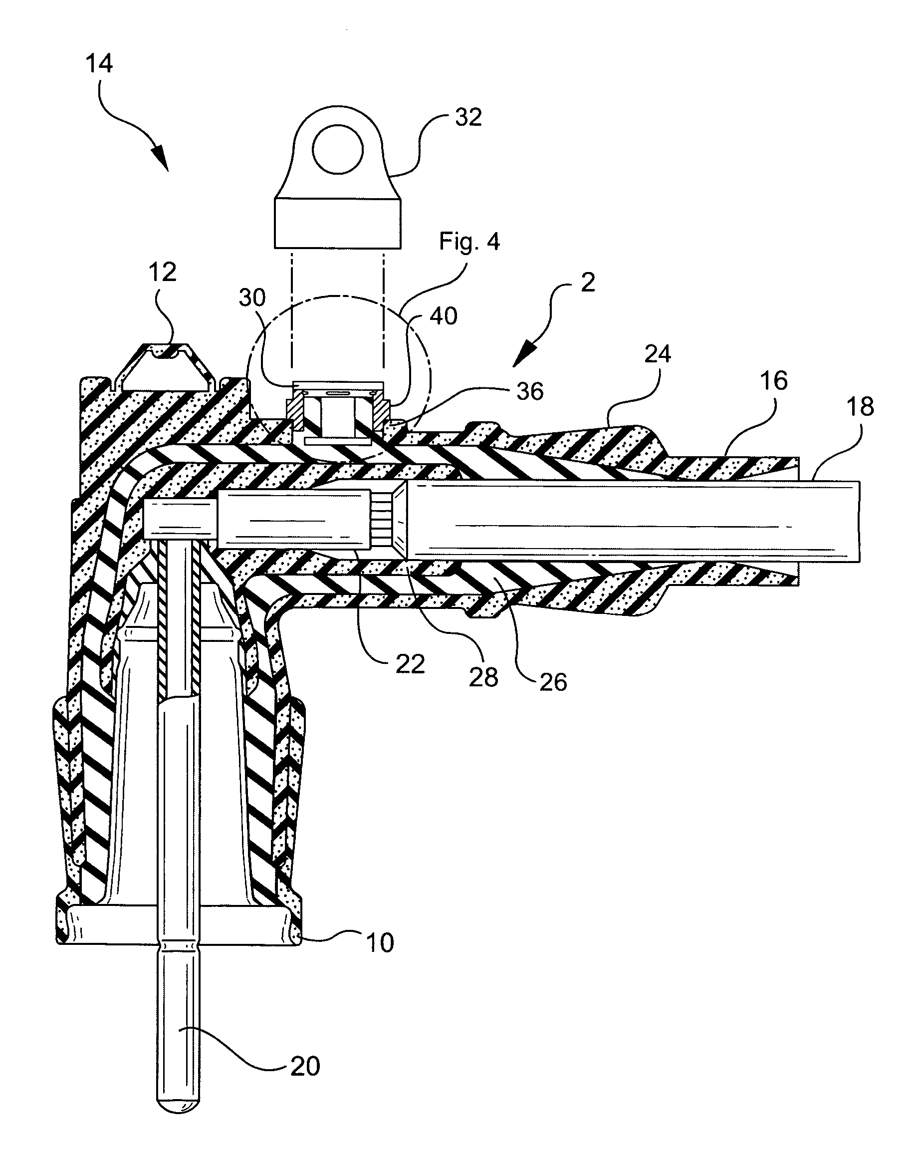
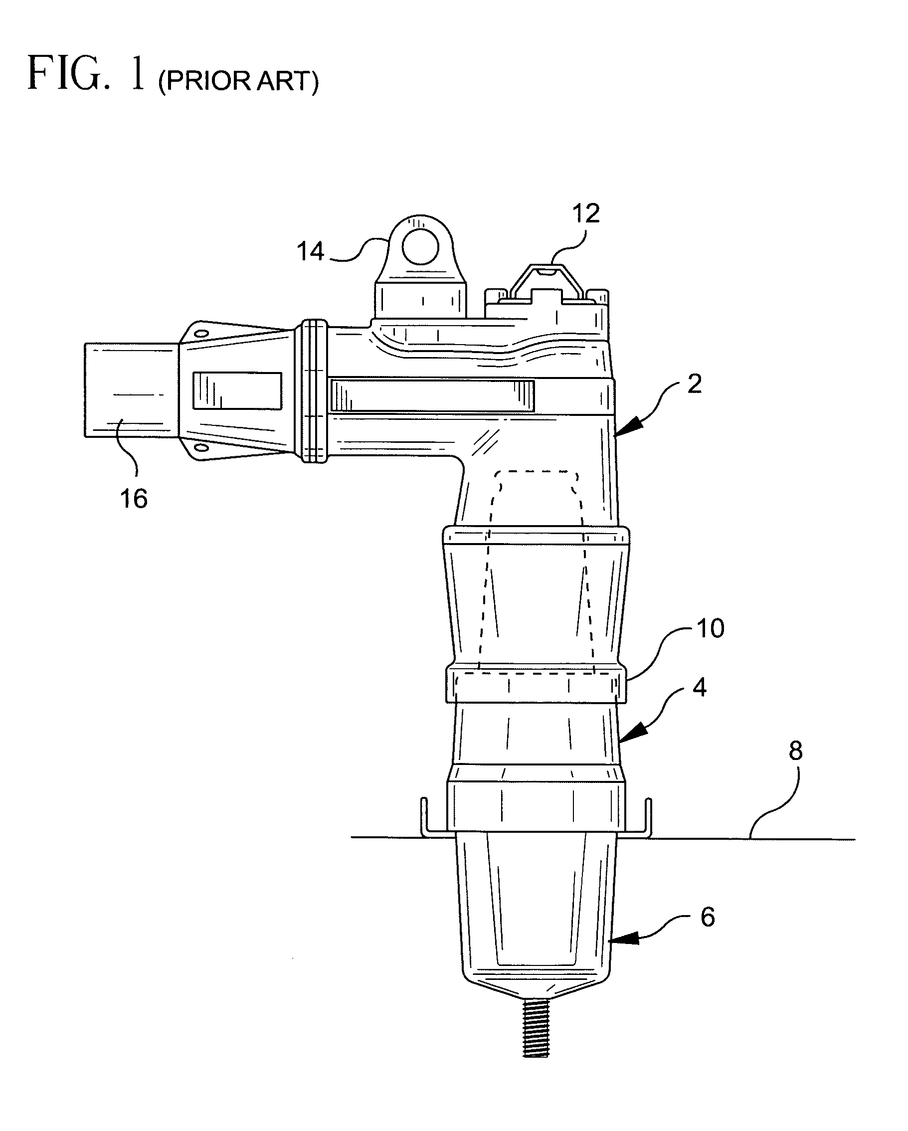
[0029]Referring first to FIGS. 1 and 2, prior art loadbreak connectors are illustrated. In FIG. 1, a power cable elbow connector 2 is illustrated coupled to a loadbreak bushing insert 4, which is seated in a universal bushing well 6. The bushing well 6 is seated on an apparatus face plate 8. The power cable elbow connector 2 includes a first end adapted for receiving a loadbreak bushing insert 4 and having a flange or elbow cuff 10 surrounding the open receiving end thereof. A power cable receiving end 16 is provided at the opposite end of the power cable elbow connector and a conductive member extends from the power cable receiving end to the bushing insert receiving end 10 for connection to a probe insertion end of the bushing insert.

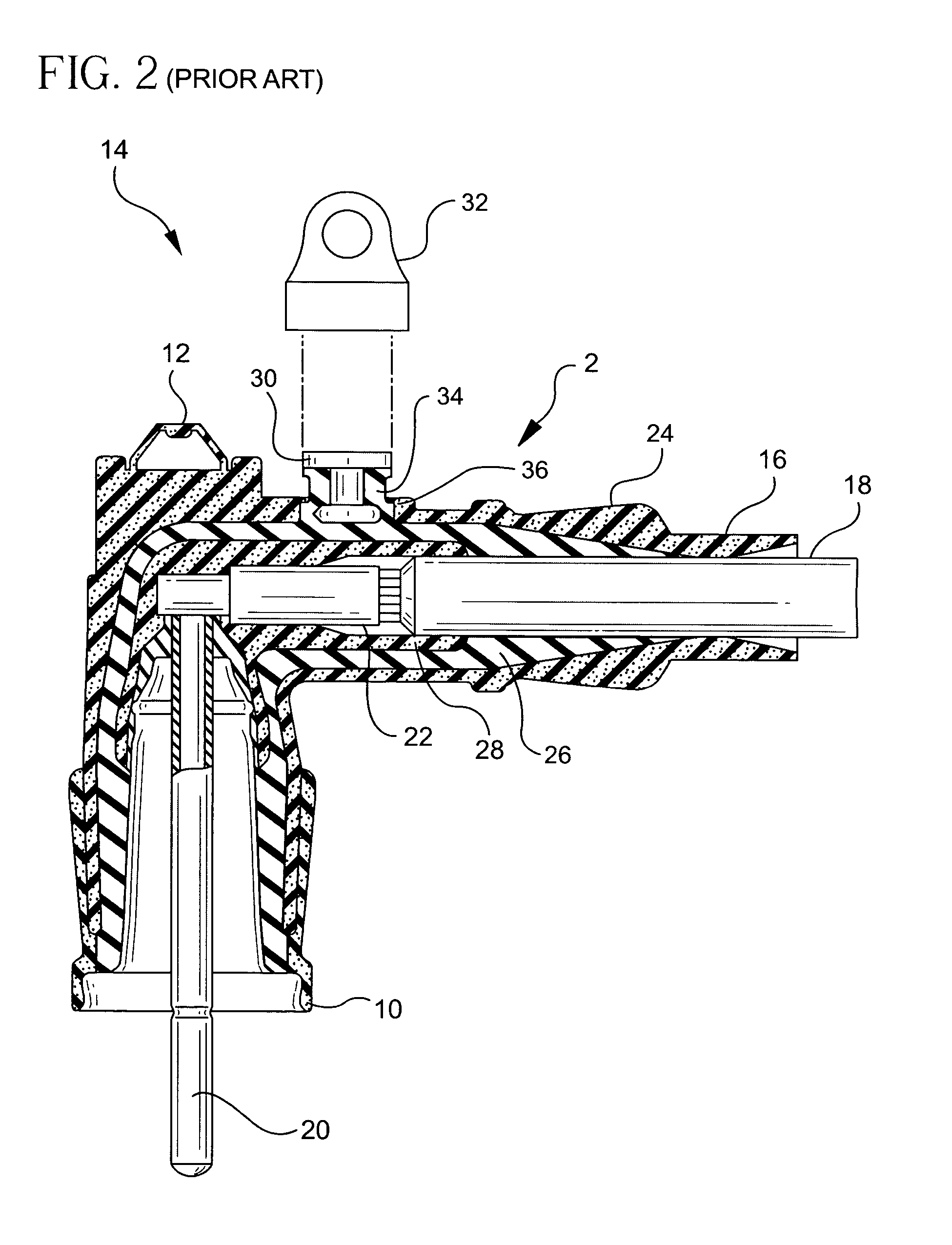
[0030]FIG. 2 is a cross-sectional view of a prior art power cable elbow connector 2, which includes a cable receiving end 16 having a cable 18 therein. The other end of the power cable elbow is a loadbreak bushing insert receiving end 10 having a prob...


PUM

PropertyMeasurementUnit
conductiveaaaaaaaaaa
voltage detection testaaaaaaaaaa
voltageaaaaaaaaaa

Abstract

In a method for forming an electrical cable connector having a voltage detection test point, an insulative shield is first molded from a thermoplastic and a conductive voltage detection test point terminal is inserted within the plastic insulative shield. After the pre-assembled insulative plastic shield and test point terminal are positioned adjacent the opening of the conductive outer shield, and after the conductive outer shield and an internal conductor are positioned within a mold cavity, an inner insulative housing is molded within the conductive outer shield and around the internal conductor.

Description

CROSS-REFERENCE TO RELATED APPLICATIONS[0001]This application is a divisional application of U.S. application Ser. No. 10 / 745,840, filed Dec. 24, 2003, now U.S. Pat. No. 6,843,685, issued Jan. 18, 2005.BACKGROUND OF THE INVENTION[0002]1. Field of the Invention[0003]The present invention relates to electrical cable connectors, such as loadbreak connectors and deadbreak connectors, and more particularly to an electrical cable connector, such as a power cable elbow connector, having a voltage detection point insulation shield, which is provided during a molding process to preserve the critical electrical interfaces of the connector.[0004]2. Description of the Prior Art[0005]Loadbreak cable connectors used in conjunction with 15, 25 and 35 kV switchgears generally include a power cable elbow connector having one end adapted for receiving a power cable and another end adapted for receiving a loadbreak bushing insert. The end adapted for receiving the bushing insert generally includes an ...

Claims


Application Information

Patent Timeline
Patent Type & Authority Patents(United States)
IPC IPC(8): H01R43/16H01R13/58H01R4/22H01R11/22H01R13/53
CPCH01R13/53H01R4/22H01R11/22H01R2201/20Y10T29/49211Y10T29/49208Y10T29/49204Y10T29/4922Y10T29/49176Y10T29/49227
Inventor BORGSTROM, ALANKNIGHT, JOHN
Owner THOMAS & BETTS INT INC
Why Eureka
Try Eureka