Tape drive and printing apparatus

Inactive Publication Date: 2006-12-19
VIDEOJET TECH INC
View PDF94 Cites 142 Cited by
  • Summary
  • Abstract
  • Description
  • Claims
  • Application Information

AI Technical Summary

Benefits of technology

[0062]In an arrangement in accordance with the fifth aspect of an exemplary embodiment, when a cassette carrying a print ribbon is to be replaced, an electronic signal can be generated to cause transport of the print sup

Problems solved by technology

Given that it is desirable to use large supply spools so as to minimize the number of times that a ribbon roll has to be replenished, this is a serious problem particularly in high speed machines where rapid ribbon transport is essential.
Such tolerances are difficult to maintain as wear in the slipping clutch over time tends to change the resistive force exerted by the clutch.
If the clutch force is too great the ribbon transport system may have inadequate power to drive the ribbon throughout the range of spool diameters from a new supply roll to an empty supply roll.
Too little clutch force and slack in the ribbon could result in overrun of the supply spool.
Given these constraints, typical printer designs have compromised performance by way of limiting the rate of acceleration, the rate of deceleration, and the maximum speed capability of the ribbon transport system.
Overall printer performance ha

Method used


Image

  • Tape drive and printing apparatus
  • Tape drive and printing apparatus
  • Tape drive and printing apparatus

Examples


Example

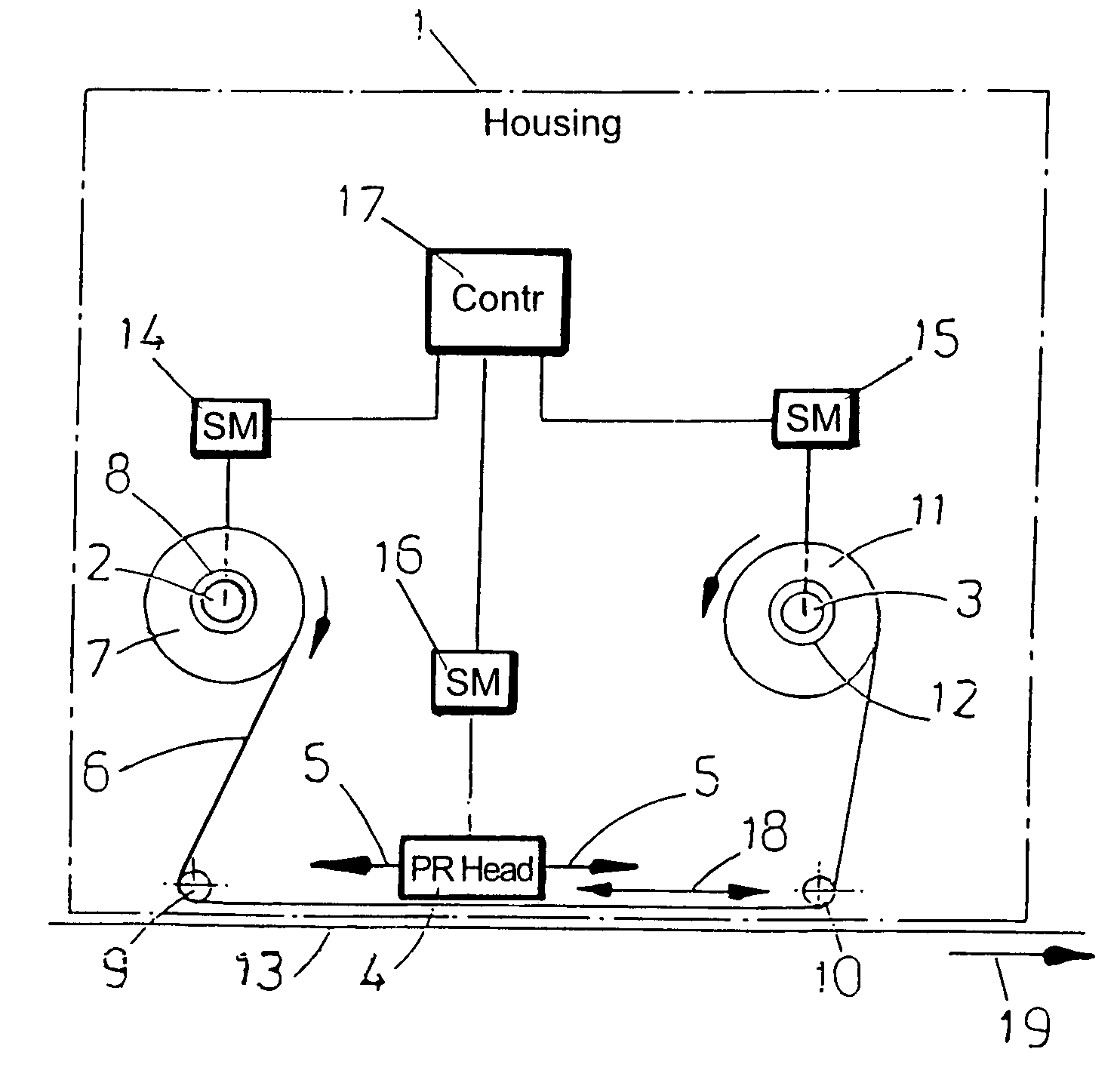
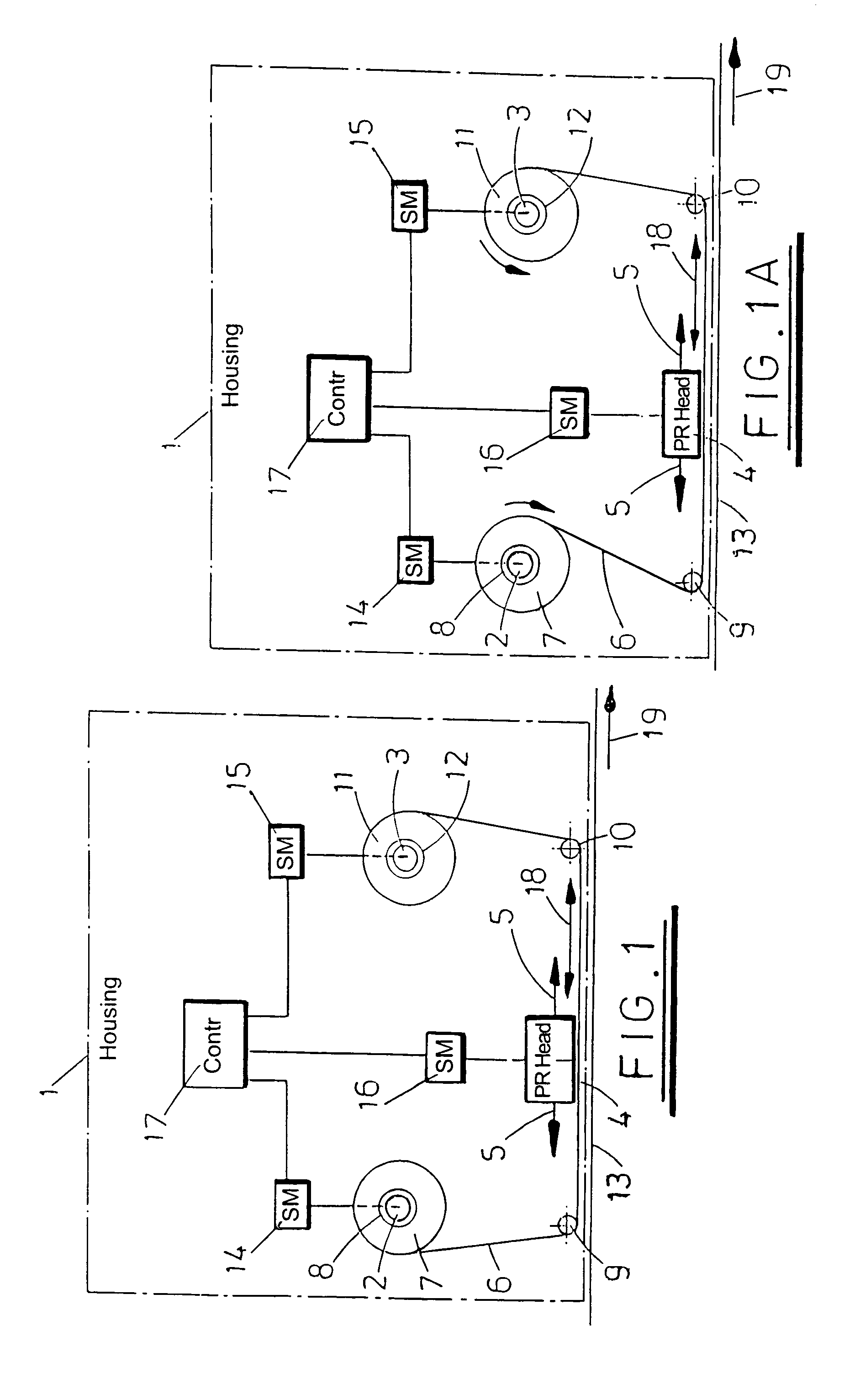
[0085]Referring to FIG. 1, the schematically illustrated printer in accordance with an exemplary embodiment has a housing represented by broken line 1 supporting a first shaft 2 and a second shaft 3. A displaceable print head 4 (PR Head) is also mounted on the housing, the print head being displaceable along a linear track as indicated by arrows 5. A printer ribbon 6 extends from a spool 7 received on a mandrel 8 which is driven by the shaft 2 around rollers 9 and 10 to a second spool 11 supported on a mandrel 12 which is driven by the shaft 3. The path followed by the ribbon 6 between the rollers 9 and 10 passes in front of the print head 4. A substrate 13 upon which print is to be deposited follows a parallel path to the ribbon 6 between rollers 9 and 10, the ribbon 6 being interposed between the print head 4 and the substrate 13.

[0086]The shaft 2 is driven by a stepper motor 14 (SM) and the shaft 3 is driven by a stepper motor 15 (SM). A further stepper motor 16 (SM) controls the...


PUM


Abstract

A tape drive for use in for example a transfer printing apparatus to drive a printer ribbon. The printer ribbon is mounted on two spools each of which is driven by a respective stepper motor. A controller controls the energization of the motor such that the ribbon is transported in at least one direction between spools mounted on the spool support. The controller is operative to energize both motors to drive the spools of ribbon in the direction of ribbon transport to achieve push-pull operations. Ribbon tension is monitored to enable accurate control of ribbon supply and ribbon take-up, the ribbon tension being monitored, for example, by monitoring power supply to the two stepper motors.

Description

BACKGROUND[0001]1. Technical Field[0002]This invention generally relates to tape drive and printing apparatus and to methods of operation for same and to apparatus and methods which may be used in transfer printers, that is printers which make use of carrier-supported inks.[0003]2. Related Art[0004]In transfer printers, a tape which is normally referred to as a printer ribbon and carries ink on one side is presented within a printer such that a print head can contact the other side of the ribbon to cause the ink to be transferred from the ribbon onto a target substrate of for example paper or a flexible film. Such printers are used in many applications. Industrial printing applications include thermal transfer label printers and thermal transfer coders which print directly onto a substrate such as packaging materials manufactured from flexible film or card.[0005]Ink ribbon is normally delivered to the end user in the form of a roll wound onto a core. The end user pushes the core ont...

Claims


Application Information

Patent Timeline
IPC IPC(8): B41J33/14B41J17/10B41J15/16B41J17/12B41J17/14B41J17/30B41J31/00B41J33/00B41J33/34B41J33/36B41J33/40B41J33/44B41J33/52B41J33/54B41J35/36B65H23/18
CPCB41J2/325B41J33/00B41J33/14B41J33/34B41J33/36B41J33/54G01B11/08B65H23/1806B65H2555/26B65H2701/372B65H2220/09B41J33/16
Inventor MCNESTRY, MARTINBUXTON, KEITHHART, PHILIP
Owner VIDEOJET TECH INC
Why Eureka
Try Eureka