Undercut anchor element that can be mounted with positive engagement

Inactive Publication Date: 2006-12-19
SIMPSON STRONG TIE IRELAND
View PDF12 Cites 23 Cited by
  • Summary
  • Abstract
  • Description
  • Claims
  • Application Information

AI Technical Summary

Benefits of technology

[0003]The object of the invention is to make further developments to the known undercut anchor element in such a way that it is ensured in every case that the anchor element is fitted with positive engagement in the appertaining fixing, i.e. the exertion of a radial spreading force on the wall of the bore in larger regions is reliably avoided.
[0004]Starting from an undercut anchor element of the type referred to in the introduction, this object is achieved according to the invention in that that the slots which form the anchoring segments in the base component extend from the end of the base component which is at the front in the fitting direction as far as and into the region of the circumferential groove, that the tightening head is so dimensioned in its axial extent and conicity that the upper boundary surface of the annular projection facing the base component butts against the free ends of the anchoring segments in the positively engaged state of the anchor element and prevents spreading of the portions of the anchoring segments which form the first truncated cone beyond abutment against the wall of an appertaining fixing bore, and that the portions of the anchoring segments which adjoin the closed sleeve portion of the base component and taken together form a first truncated cone are longer than the portions of the anchoring segments which adjoin them and are at the front in the fitting direction and together form the second truncated cone, whereby the cone angle formed by generatrices of the outer boundary surface of the first truncated cone lying diametrically opposite in each case encloses an acute angle of less than 30°, preferably less than 20°, and the cone angle formed by generatrices of the outer boundary surface of the second truncated cone lying diametrically opposite encloses an obtuse angle of more than 150°, preferably more than 160°, and the generatrices of the boundary surfaces of the first and second truncated cone intersect at an angle in the range between 85° and 95°, preferably substantially at right angles. In this way it is ensured that the locking segments can only be pivoted out by such an amount that, with the exception of the forces exerted by the cutting edges, they cannot exert any spreading force on the wall of the bore.
[0005]In this case the slots which form the anchoring segments in the base component advantageously extend from the end of the base component which is at the front in the fitting direction only as far as the groove side wall delimiting the circumferential groove. Thus this sleeve portion of the base component is closed all round and cannot expand radially even under the effect of high axial forces, so that it is ensured that the base component also cannot expand radially in its portion lying above the anchoring segments.

Problems solved by technology

Because of the high radial spreading forces which are necessary for the anchoring by frictional engagement, the use of such spreading dowels is only possible in substrates made from concrete material or also solid stone or rock material which can be subjected to a correspondingly high load, and even with concrete substrates which can be loaded sufficiently it is only possible to provide fixing bores with considerable clearance from the boundary of the respective concrete component in order to ensure that the fixing bore does not break open when the spreading dowel is mounted.

Method used


Image

  • Undercut anchor element that can be mounted with positive engagement
  • Undercut anchor element that can be mounted with positive engagement
  • Undercut anchor element that can be mounted with positive engagement

Examples


Embodiment Construction

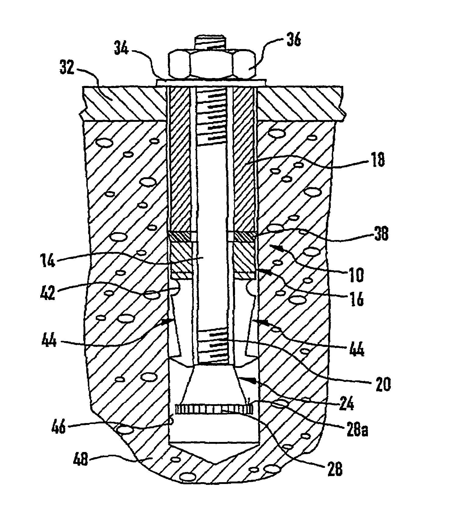
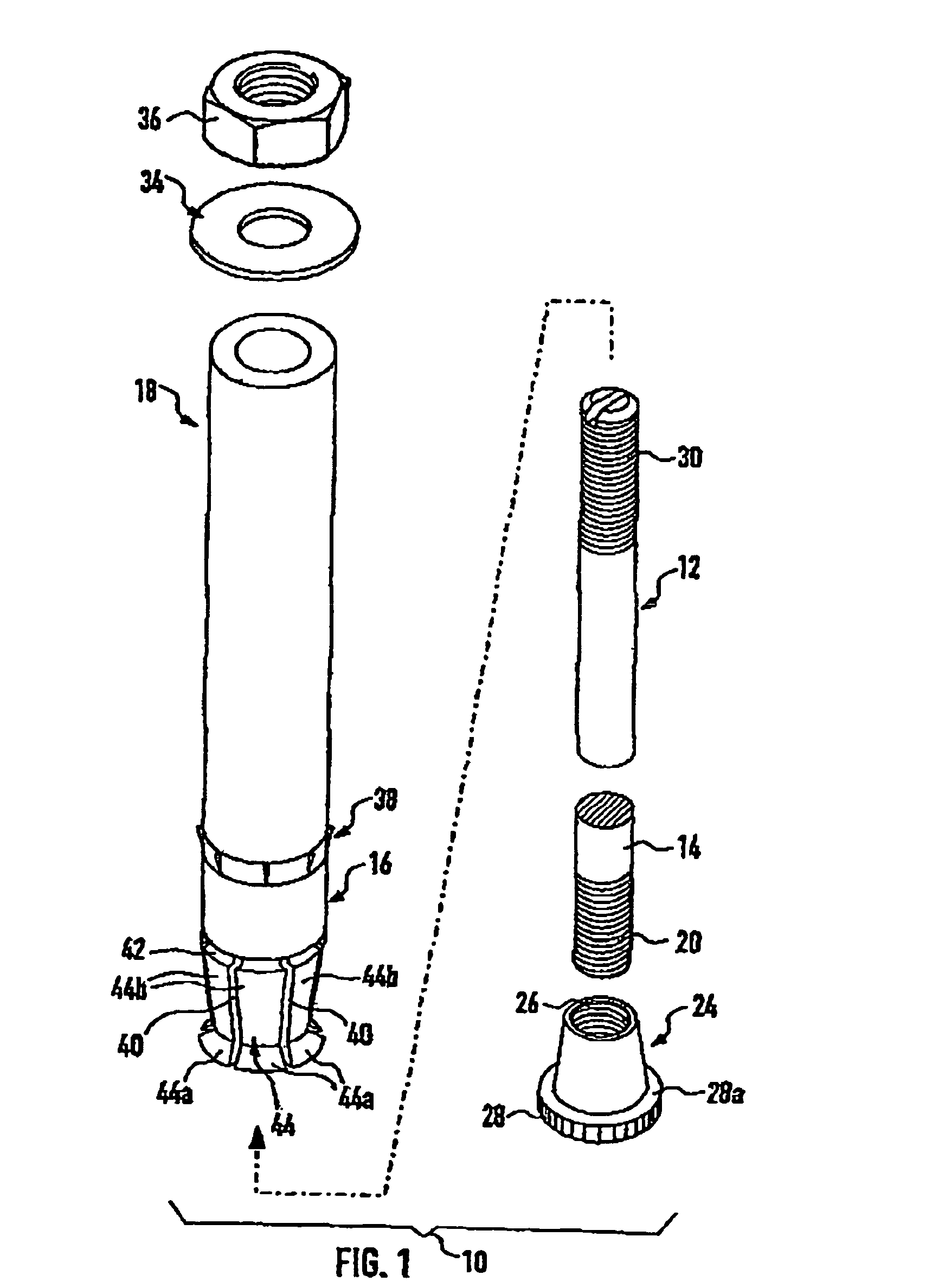
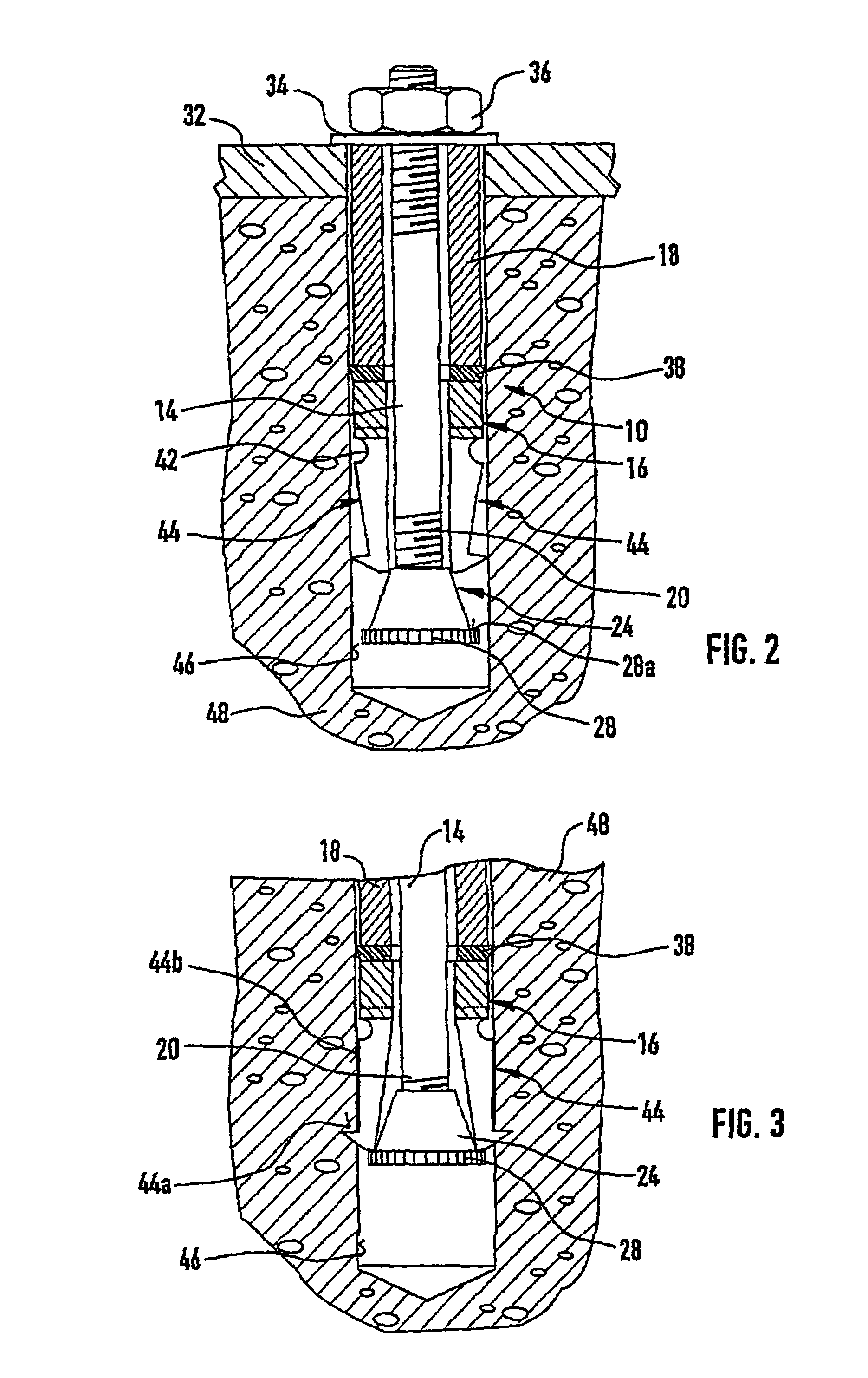
[0010]The undercut anchor element which is illustrated in the drawings and is denoted in its entirety by 10 is composed of the components which are explained in detail below, namely an elongate anchor bolt 12, a tubular base component 16 disposed so as to be longitudinally displaceable on the cylindrical shank 14 of the anchor bolt, a spacer sleeve 18, a tightening head 24 which in the illustrated embodiment is screwed on a thread 20 of the anchor bolt 12 at the lower end in the drawing and is provided with a threaded bore 26 which widens conically from the shank 14 of the anchor bolt. On the end of the tightening head 24 which is innermost in the bore a circumferential annular projection 28 is provided which projects radially and is provided with a knurling on its circumferential surface and of which the upper radial boundary surface 28a facing the base component forms a stop surface, the function of which will be explained below. On its end region opposite the tightening head 24, ...


PUM


Abstract

An undercut anchor element comprising a shank of an anchor bolt. The shank passes through a base part, which is provided for effecting an anchoring, passes through a spacer sleeve, and at the end thereof is provided with a tightening head. The tightening head can be pulled inside the base part, which is subdivided into anchoring segments by slots provided over a portion of the length of the base part. The slots lead from the front free end of the base part up and into the area of an encircling groove. The anchoring segments have the outer shape of two truncated cones which coincide with their ends that have a smaller diameter. The truncated cone that is located in front in a direction of mounting has an obtuse cone angle of greater than 150° and the adjoining truncated cone has an acute cone angle of less than 30°.

Description

BACKGROUND OF THE INVENTION[0001]The invention relates to an undercut anchor element with an anchor bolt, the elongate cylindrical shank of which is provided on its end which is to the rear in the fitting direction with a fixing head or a nut screwed onto a thread and has on its end which is to the front in the fitting direction a tightening head which widens in the shape of a truncated cone with a radially projecting annular projection provided on its free end, on which there is displaceably mounted a tubular base component which has multiple slots extending from its end which is at the front in the fitting direction and over a part of its length and forms a number of anchoring segments in the slotted region, the said base component having an internal diameter substantially equal to or somewhat greater than the external diameter of the cylindrical shank and having in its outer face a circumferential groove spaced from the end which is at the front in the fitting direction, wherein ...

Claims


Application Information

Patent Timeline
Patent Type & Authority Patents(United States)
IPC IPC(8): F16B13/06
CPCF16B13/066
Inventor LIEBIG, HEINRICHLIEBIG-HUNDIUS, LEGAL REPRESENTATIVE, INGRIDLIEBIG, LEGAL REPRESENTATIVE, HEINZ JOACHIM
Owner SIMPSON STRONG TIE IRELAND
Why Eureka
Try Eureka