Cover device and method for electrical connector

a technology for electrical connectors and devices, applied in the field of electrical connectors, can solve problems such as the risk of harm to connectors, and achieve the effect of improving the registration of locations

Inactive Publication Date: 2006-12-19
GM GLOBAL TECH OPERATIONS LLC
View PDF3 Cites 21 Cited by
  • Summary
  • Abstract
  • Description
  • Claims
  • Application Information

AI Technical Summary

Benefits of technology

[0019]Another aspect of the invention is that the contact pattern may lie on multiple surfaces of the cover in order to provide improved locating regi

Problems solved by technology

There is a risk of harm to the connector each time

Method used


Image

  • Cover device and method for electrical connector
  • Cover device and method for electrical connector
  • Cover device and method for electrical connector

Examples


Embodiment Construction

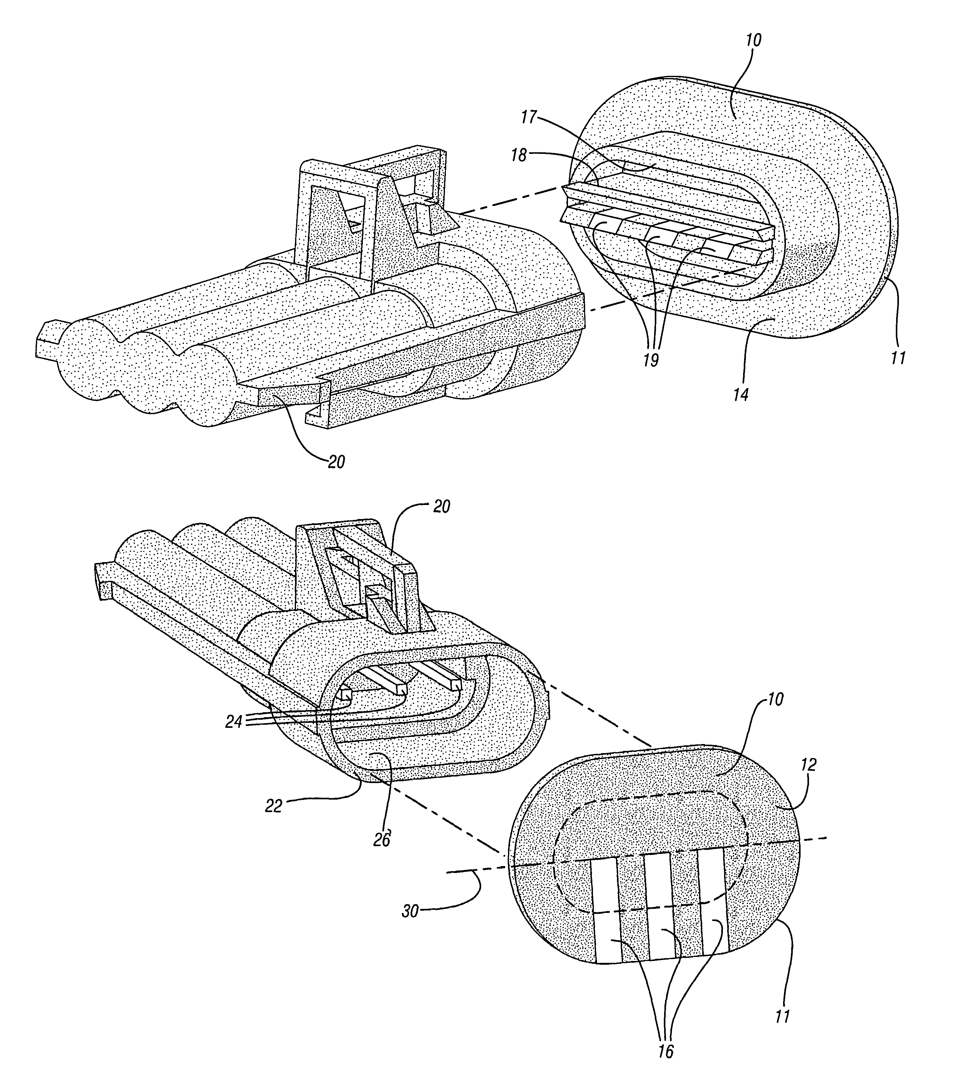
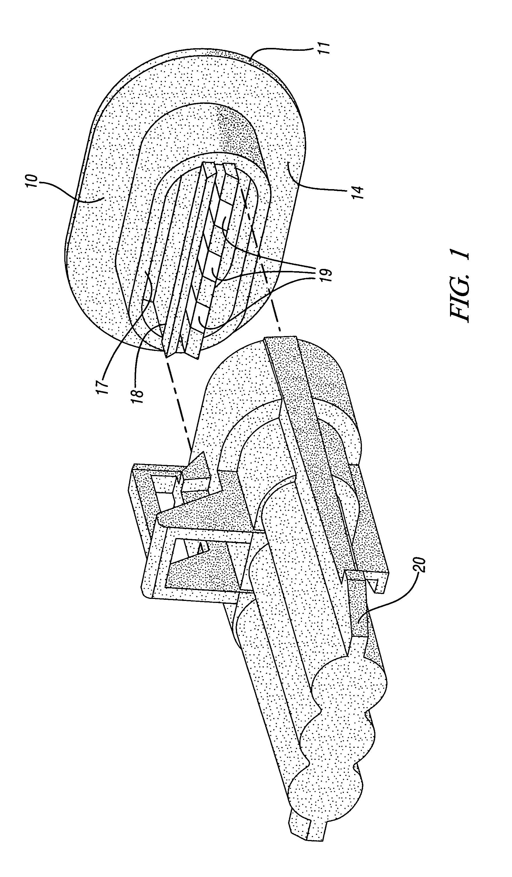
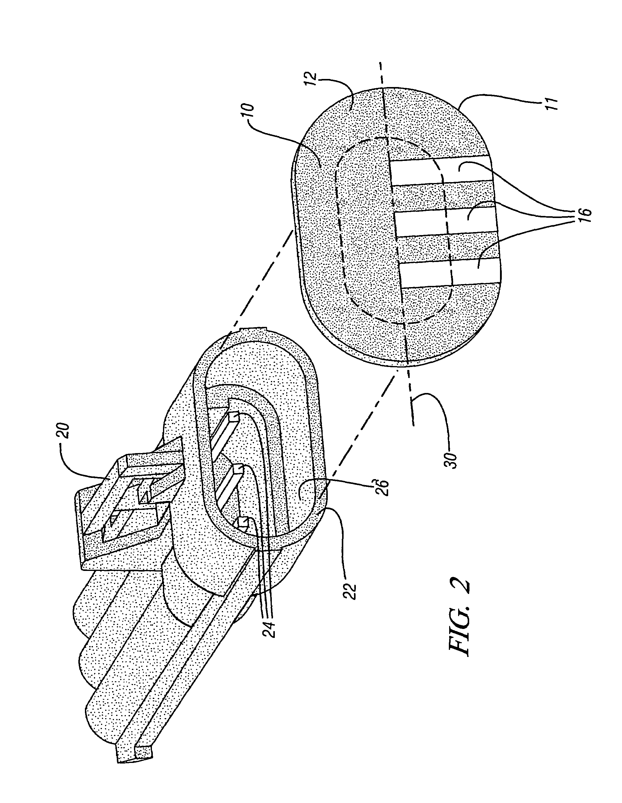
[0024]Referring now to the drawings, wherein the showings are for the purpose of illustrating the invention only and not for the purpose of limiting the same, FIGS. 1 and 2 show first and second perspective views of an exemplary device, which has been constructed in accordance with an embodiment of the present invention.

[0025]The device 10 provides a covering for a mating end 22 of an electrical connector 20 having conductive terminals 24. The electrical connector 20 shown is a conventional connector having three male conductive terminals arranged in a single plane. A typical application for the electrical connector is for an automotive component device, although the invention is not intended to be so limited.

[0026]The device 10 has an external end 12 and an internal end 14, and is attachable to the mating end 22 of the electrical connector 20. When the device is attached to the electrical connector, it substantially completely covers the end 22 and creates an environmental seal the...


PUM


Abstract

A detachable device for covering an end of an electrical connector, comprising a non-conductive cover, sealingly attachable, and completely covering the mating end of the connector. An external end of the cover is generally planar with electrically conductive pads corresponding to the conductive terminals of the connector, and electrically connecting the pads to the terminals. The electrically conductive pads are arranged in a pattern, oriented to provide a single line-of-sight for machine recognition.

Description

TECHNICAL FIELD[0001]This invention pertains generally to electrical connectors, and more specifically to a device and method to cover a connector.BACKGROUND OF THE INVENTION[0002]Electrical connectors are employed in various applications to provide ready attachment of a component into a system, and subsequent detachment when appropriate or necessary, such as for component service, testing, or replacement. An electrical connector is operable to transmit electrical information between the system and the component, and is often an integral element of a wiring harness. A connector has requirements for quality, reliability, and durability, related to the specific application and environmental conditions. An electrical connector may be expected to provide connectors for wiring systems which transmit analog and digital electrical signal data, electrical power, and electrical grounding.[0003]An electrical connector may be assembled in one location, and transported to a second location for ...

Claims


Application Information

Patent Timeline
IPC IPC(8): H01R13/44
CPCH01R13/5213H01R31/06H01R2201/20Y10S439/912
Inventor FONVILLE, CARL E.HAWKINS, ROLAND C.
Owner GM GLOBAL TECH OPERATIONS LLC
Why Eureka
Try Eureka