
Dynamic phantom for radiation therapy

a radiation therapy and dynamic technology, applied in radiation therapy, therapy, instruments, etc., can solve the problems of significant target motion, and achieve the effect of facilitating three-dimensional motion and studying the ramifications of dynamic target motion

Active Publication Date: 2006-12-19
COMPIZED IMAGING REFERENCE SYST
View PDF11 Cites 28 Cited by
  • Summary
  • Abstract
  • Description
  • Claims
  • Application Information

AI Technical Summary

Benefits of technology

"The present invention is about a new way of delivering radiation therapy to targets in the lung and liver. These targets can move a lot, which makes it challenging to deliver the radiation accurately. The invention is a special phantom that can mimic the movement of these targets. The phantom is designed to help researchers study the effects of different types of radiation therapy and how to make them more effective. The invention can help improve the precision of radiation therapy and make it more effective in treating lung and liver cancer."

Problems solved by technology

The delivery of large conformal doses to such targets poses numerous challenges, which can include the presence of significant degrees of target motion.

Method used


Image

  • Dynamic phantom for radiation therapy
  • Dynamic phantom for radiation therapy
  • Dynamic phantom for radiation therapy

Examples


Embodiment Construction

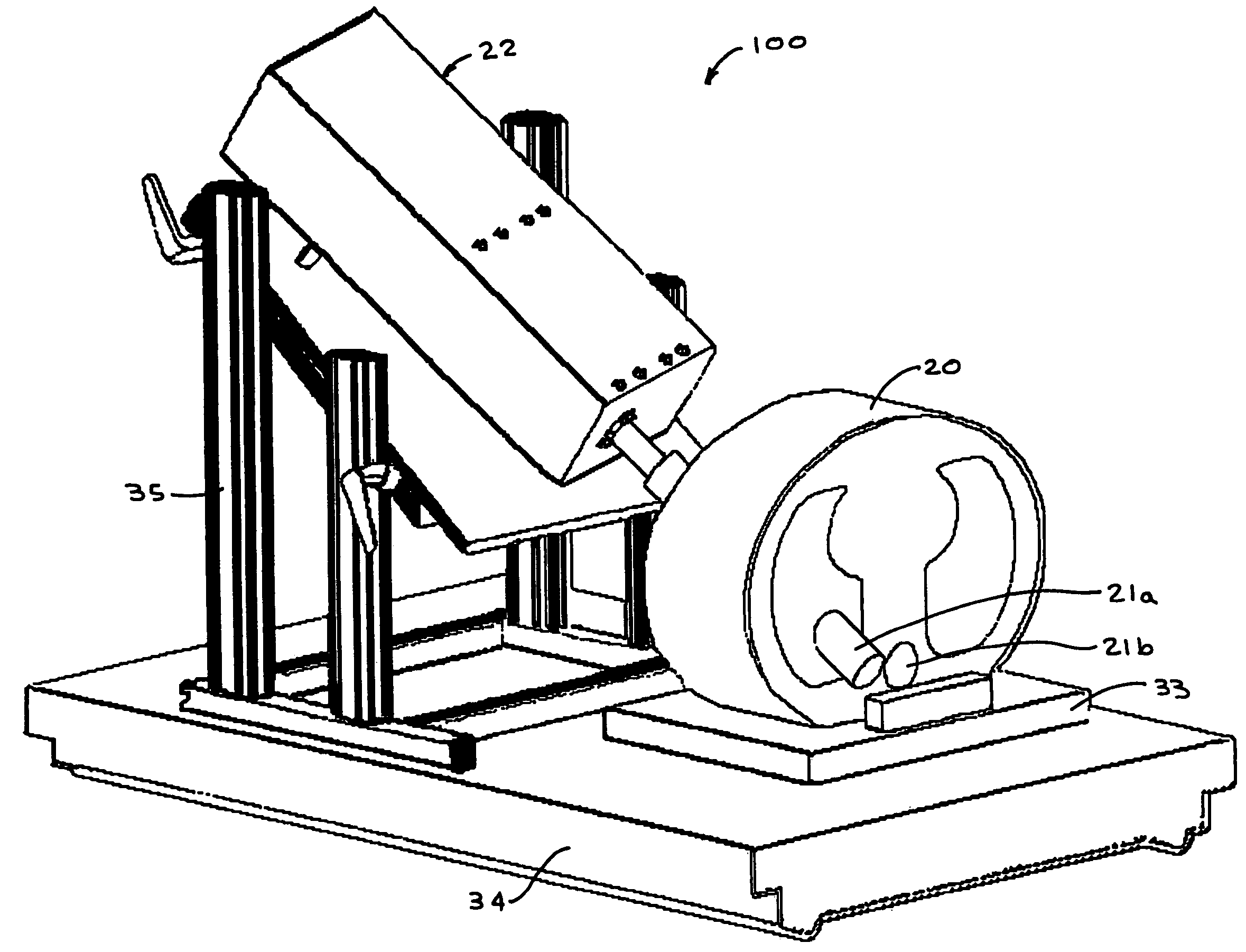
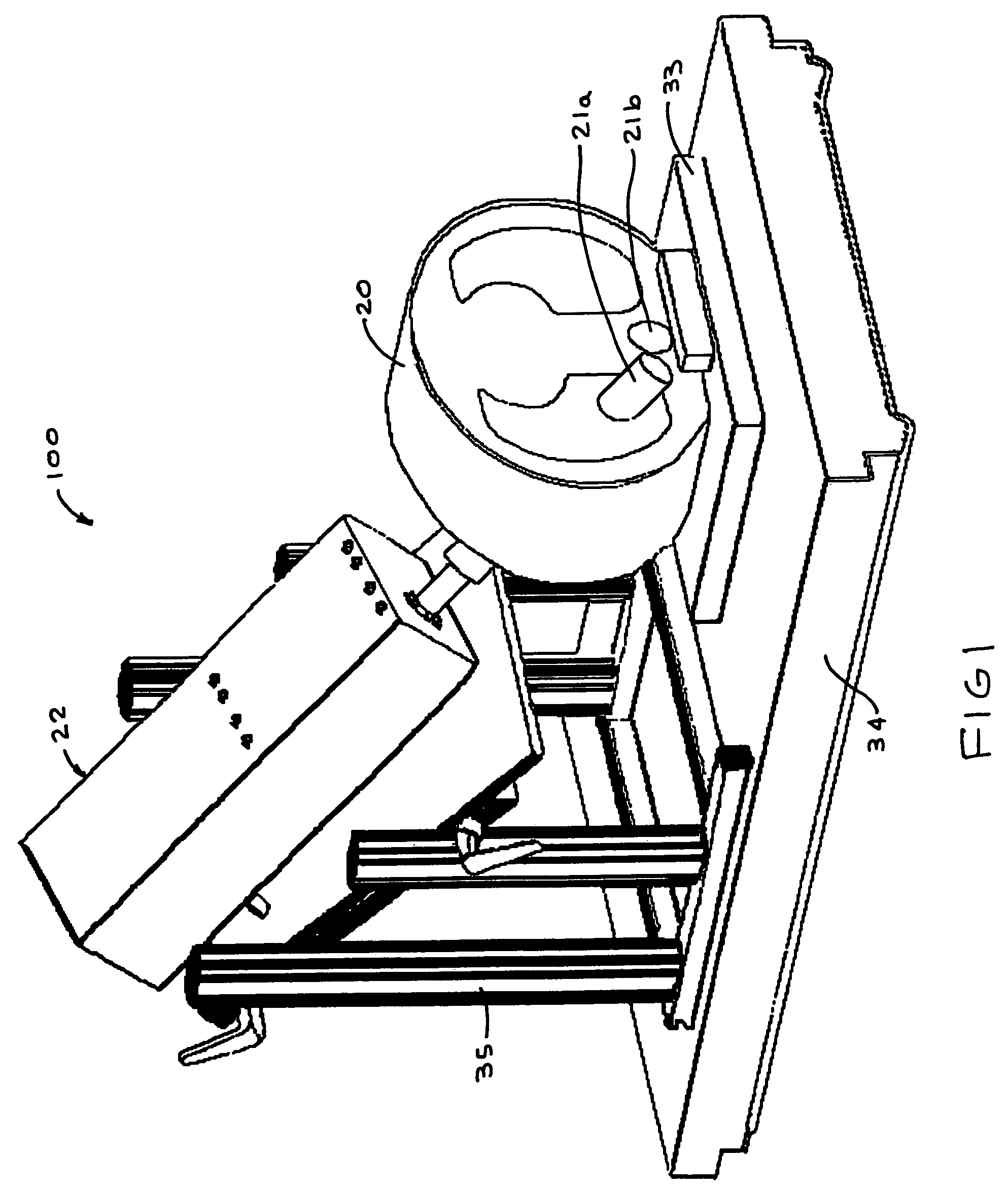
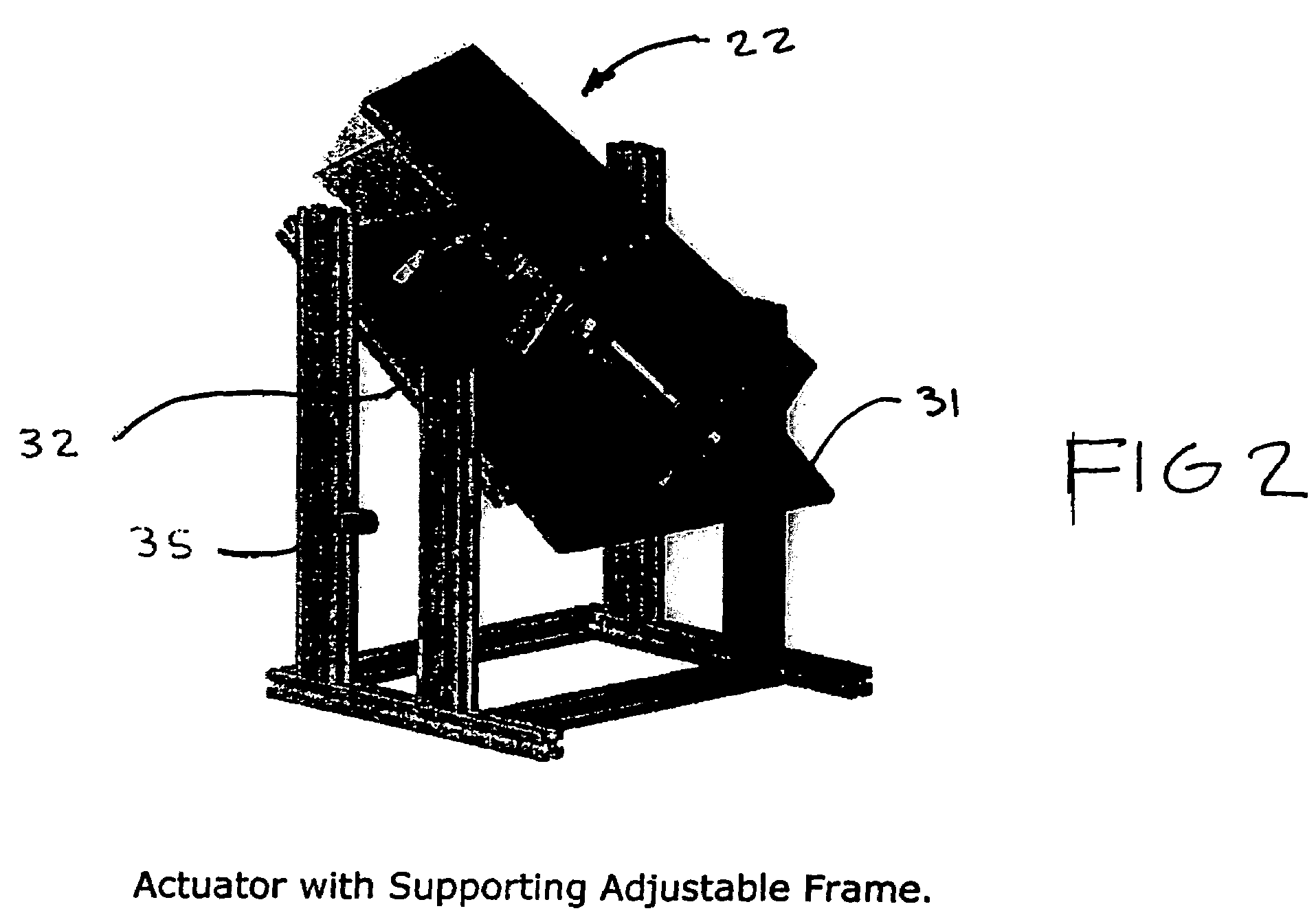
[0068]The preferred embodiment of the dynamic thorax phantom (generally designated 100 in the Figures) comprises four sub-component systems: tissue equivalent phantom 20 and tissue equivalent rod 21; motion actuator assembly (generally designated 22 in the Figures); motion controller assembly (generally designated 23 in the Figures), which includes controllers, drivers and electronics; and personal computer interface and software (generally indicated as 26 in the Figures).

[0069]In the preferred embodiment of the invention, the thorax phantom 20 is approximately 15 cm in longitudinal length, 30 cm wide and 20 cm high. It includes pseudo anthropomorphic, tissue equivalent lungs and spine. Two holes 27 and 28 run longitudinally through the phantom, one (27) parallel to the bottom and side surfaces the other (28) off angle in both directions. A tissue equivalent rod 21a and 21b, having material densities the same as that of the surrounding phantom 20, are placed within the holes 27 and ...


PUM


Abstract

The present invention is a thorax phantom that enables simulation of tumor motion within a tissue equivalent material. The system consists of a tissue equivalent epoxy phantom representing a 15 cm axial section of the human thorax that includes simplified spine and lung anatomies. Within the phantom are thru rods of similar tissue density. The rods are attached to a computer-controlled actuator that facilitates both linear and rotational motion of the rods within the phantom. A plurality of tumor targets and radiation detectors can be placed within the rods at various locations thereby enabling the simulation of respiratory and cardiac induced tumor motions within the phantom and assessment of the effects of these motions on image acquisitions, treatment planning and radiation treatment delivery.

Description

CROSS REFERENCE TO RELATED APPLICATIONS[0001]Inventors claim priority benefits of Provisional Patent Application Ser. No. 60 / 556,640 Filed on Mar. 26, 2004.FIELD OF INVENTION[0002]The present invention relates generally to diagnostic imaging and radiation therapy systems and more specifically to a method and apparatus for evaluation of said systems and their capability to correctly compensate for dynamic target motions in both image acquisitions, treatment planning and dose delivery situations, by providing a tissue equivalent phantom member having an operator controllable target member dynamically disposed within the phantom member.BACKGROUND OF THE INVENTION[0003]It is estimated that approximately 50% of all cancer patients will undergo some form of radiation therapy as part of their curative treatment. The objective of radiation therapy is to accurately focus lethal doses of ionizing radiation to cancer cells while minimizing dose to healthy tissues surrounding the cancer. Toward...

Claims


Application Information

Patent Timeline
Patent Type & Authority Patents(United States)
IPC IPC(8): G12B13/00A61N5/10G01R33/58
CPCA61N5/1048G01R33/58A61N2005/1072A61N2005/1076
Inventor VARCHENA, VLADMIRDEVLIN, MARK T.ZERHOUNI, MOUSTAFAMOORE, TERRY W.
Owner COMPIZED IMAGING REFERENCE SYST
Learn More