Detection warning system for caregivers in a home

a warning system and caregiver technology, applied in the field of detection warning system, can solve the problems of monitoring system, system not designed for home use, and inability to summon nurses

Inactive Publication Date: 2006-12-19
RILEY JAMES A +1
View PDF6 Cites 22 Cited by
  • Summary
  • Abstract
  • Description
  • Claims
  • Application Information

AI Technical Summary

Problems solved by technology

Hospitals have been using monitoring systems to alert a nurses station, however, these monitoring systems will operate only with a patient physically capable of pushing a button to summon a nurse for assistance.
The medical industry has objected to these systems since the physically and mentally challenged patient may not be able to utilize this system and patients who roam or fall out of bed will not be able to summon the nurse for help.
These systems are not designed for home use.
Many of the mentioned monitoring systems, from the expensive programmable data to the pressure pad systems, do not possess reliability, flexibility or ease of use and cannot be used in a home.
The fan-shaped PIR systems detect any movement in a room, therefore, may trigger false alarms when a nurse enters to assist the patient.
These systems require professional installation into a nurses station, therefore, are not designed for home use.
These systems are used in hospitals, however, are not designed for home use.
(a) The manufacturing of data processor systems requires an engineer or technician to program the processor and retrofit into an existing nurses station which would eliminate home use and the need for the portability necessary for caregivers in a home. Manufacturing, installation and repair of this system would prove to be very expensive.
(b) Fan-shaped zone detection systems may detect others in the room and cannot differentiate between the patient, nurse, and visitors which may trigger false alarms. When a nurse or visitor wishes to enter the patient's room, the zone system has to be turned off to approach the patient's bedside, as a result, interfering with patient care. Once installed by a professional into the nurses station, this system becomes permanent. As a result of the zone detection being triggered by a person entering the patient's room, this system would not be suitable for home use.
(c) Installation of a pressure pad sensing device in the hospital bed requires a cable or other transmission means used to connect this sensing device to an external circuit. This cable may interfere with the patient when the patient exits the bed or with the patient's care. If the patient moves or sits up in bed, unwanted signals will trigger a false alarm. Soiled pressure pads must be replaced periodically resulting in additional nurse's time and expense. The pressure pad sensing devices will not activate the alarm when the patient weighs less than a certain prescribed weight.
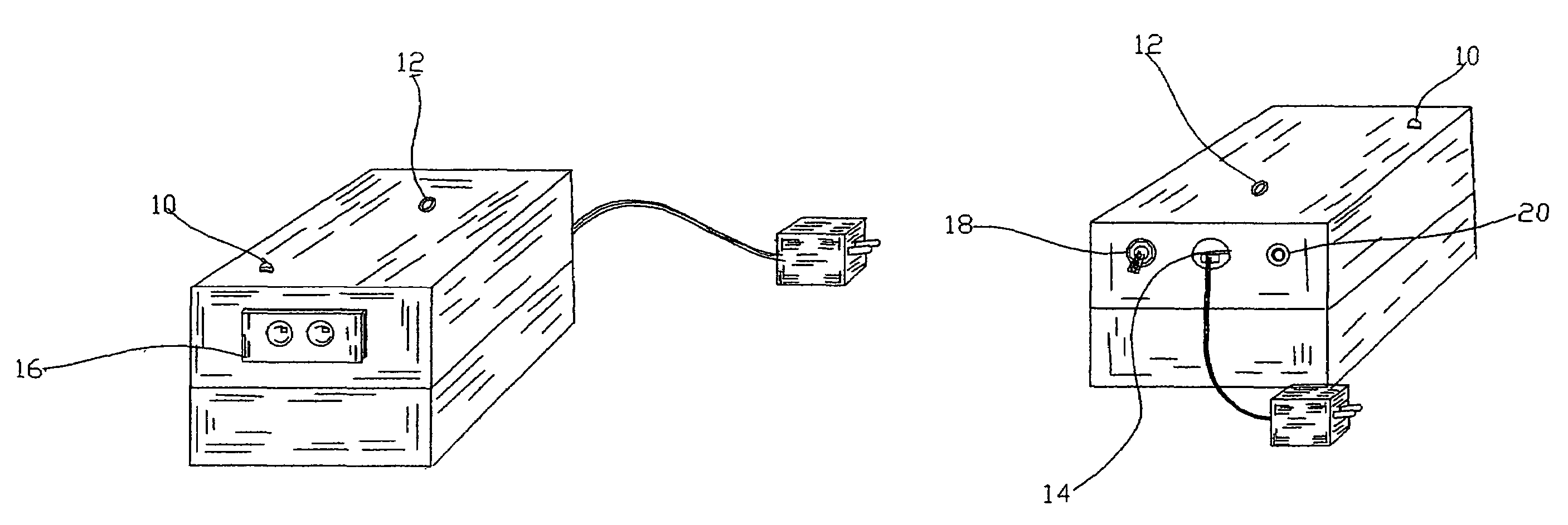
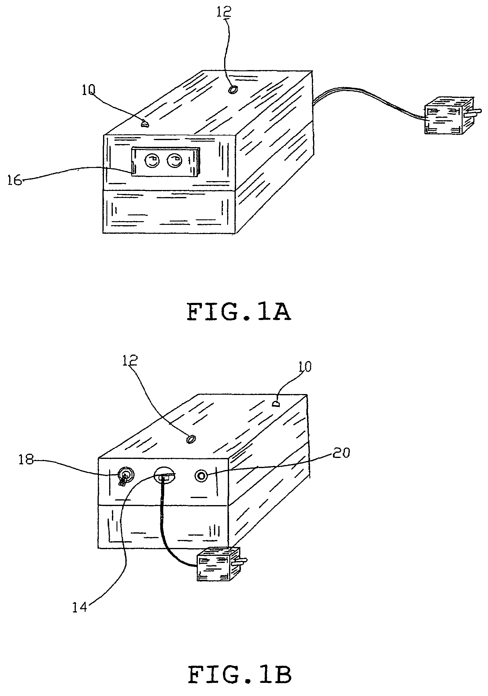
(d) A patient monitoring system comprising of an array of radiant energy emitters corresponding to an array of radiant detectors installed in a headboard and footboard of a hospital bed becomes a permanent fixture of the bed. Emitters and detectors such as these require professional installation. The zone of infrared energy which covers the bed detects patient movement or a patient's bed coverings which may trigger false alarms. The system has to be turned off when a nurse has to assist the patient. Systems such as this were not intended for home use.
(e) Some patient monitoring systems are designed utilizing individual components. To incorporate all the individual electronic components necessary to manufacture an instrument would not be cost effective, flexible or easy to fabricate. Replacing damaged components would prove to be expensive.
(f) These monitoring systems do not afford the capability of selecting different modes of detection.
(g) The patient monitoring systems are permanently retrofitted into a nurses station, therefore, are not able to operate on an independent battery power pack.
(h) The electronic circuits for most of these patient monitoring systems do not incorporate safety devices such as fuses or circuit breakers.

Method used


Image

  • Detection warning system for caregivers in a home
  • Detection warning system for caregivers in a home
  • Detection warning system for caregivers in a home

Examples


Embodiment Construction

Description—FIGS. 1A and 1B—Preferred Embodiment

[0099]A preferred embodiment of the portable infrared emitter detector base unit of the present invention is illustrated in FIG. 1A and 1B. This portable infrared emitter detector base unit houses an emitter and detector (not shown) within an emitter detector module 58 (FIG. 9) which emits a narrow, infrared beam. This narrow, infrared beam is focused through a lens (FIGS. 1A and 2) onto an external reflector 44 (FIGS. 5, 6, 7 and 8). When the portable infrared emitter detector base unit and external reflector 44 are in proper alignment, alignment light 10 will be illuminated. When the narrow, infrared beam is interrupted, the portable infrared emitter detector base unit senses the narrow, infrared beam has been obstructed which activates a transmitter (not shown) in a transmitter module (FIG. 9) transmitting a pulse modulated signal and a transmit light 12 located in the portable infrared emitter detector base unit. This transmitted p...


PUM


Abstract

A detection warning system for caregivers in a home alerting a caregiver when a person exits a room, bed or walk through a doorway. This system comprises of two enclosures and an external reflector. A portable infrared emitter detector enclosure houses an emitter with a narrow, infrared beam, detector and transmitter. A portable receiving enclosure houses a receiver with an adjustable audio alarm. An emitter in the emitter detector enclosure emits an infrared beam to the reflector, which reflects the beam back to the detector. The detector senses when the beam is obstructed from reaching the reflector and energizes the transmitter. The transmitter receives the signal from the transmitter activating the adjustable audio alarm alerting a caregiver.

Description

CROSS-REFERENCE TO RELATED APPLICATIONS[0001]This Application claims priority from U.S. Provisional Application No. 60 / 552,049 filed on Mar. 10, 2004, entitled “A Detection Warning System for Caregivers in a Home.”BACKGROUND[0002]1. Field of Invention[0003]This invention relates to a detection warning system specifically to a portable system which detects an individual interrupting a narrow, infrared beam and alerts a caregiver anywhere in a home with an adjustable audio alarm.[0004]2. Description of Prior Art[0005]Hospitals have been using monitoring systems to alert a nurses station, however, these monitoring systems will operate only with a patient physically capable of pushing a button to summon a nurse for assistance. The medical industry has objected to these systems since the physically and mentally challenged patient may not be able to utilize this system and patients who roam or fall out of bed will not be able to summon the nurse for help. These systems are not designed fo...

Claims


Application Information

Patent Timeline
Patent Type & Authority Patents(United States)
IPC IPC(8): G08B23/00
CPCG08B21/0469
Inventor RILEY, JAMES A.RANDALL, TAMI L.
Owner RILEY JAMES A
Why Eureka
Try Eureka