Voice enhancement device by separate vocal tract emphasis and source emphasis

a technology of source emphasis and voice enhancement, which is applied in the field of voice enhancement devices, can solve the problems of excessive input into the speaker of the portable telephone, the received voice of the portable telephone becoming difficult to hear, and the conversely deteriorating sound quality, so as to achieve the effect of extremely easy to hear voice clarity

Inactive Publication Date: 2006-12-19
FUJITSU CONNECTED TECH LTD
View PDF20 Cites 23 Cited by
  • Summary
  • Abstract
  • Description
  • Claims
  • Application Information

AI Technical Summary

Benefits of technology

[0024]The present invention was devised in light of the problems encountered in the prior art; it is an object of the present invention to provide a voice enhancement method which makes the voice clarity extremely easy to hear, and a voice enhancement device applying this method.
[0030]As a sixth aspect, the voice enhancement device that achieves the abovementioned object of the present invention is a voice enhancement device comprising a signal separating part which separates the input voice signal into sound source characteristics and vocal tract characteristics, a characteristic extraction part which extracts characteristic information from the abovementioned vocal tract characteristics, a corrected vocal tract characteristic calculating part which determines vocal tract characteristic correction information from the abovementioned vocal tract characteristics and the abovementioned characteristic information, a vocal tract characteristic correction part which corrects the abovementioned vocal tract characteristics using the abovementioned vocal tract characteristic correction information, a signal synthesizing part which synthesizes the abovementioned sound source characteristics and the corrected vocal tract characteristics from the abovementioned vocal tract characteristic correction part, and a filter which enhances some of the frequency bands of the abovementioned signal synthesized by the abovementioned signal synthesizing part.

Problems solved by technology

Accordingly, the problem of the received voice of portable telephones becoming difficult to hear as a result of ambient noise arises.
However, if the received sound volume is increased to an excessive extent, there may be cases in which the input into the speaker of the portable telephone becomes excessive, so that sound quality conversely deteriorates.
Furthermore, the following problem is also encountered: namely, if the received sound volume is increased, the burden on the auditory sense of the listener (user) is increased, which is undesirable from the standpoint of health.
Generally, when ambient noise is large, the clarity of voice is insufficient, so that the voice becomes difficult to hear.
In the case of such a method, however, not only the high-band components, but also noise (transmission side noise) components contained in the received voice, are enhanced at the same time, so that the sound quality deteriorates.
In this method, however, there is no guarantee that the voice formants will always fall within the split frequency bands; accordingly, there is a danger that components other than the formants will also be enhanced, so that the clarity conversely deteriorates.
In the abovementioned conventional technique, in the case of methods in which the sound quantity is increased, there are cases in which an increase in the sound quantity results in an excessive input into the speaker, so that the playback sound is distorted.
Furthermore, if the received sound quantity is increased, the burden on the auditory sense of the listener (user) is increased, which is undesirable from a health standpoint.
Furthermore, in conventional methods using a high-band enhancement filter, if simple high-band enhancement is used, high bands of noise other than the voice are enhanced, so that the feeling of noise is increased, which does not always lead to an improvement in clarity.
Moreover, in conventional methods using a band splitting filter, there is no guarantee that the voice formants will always fall within the split frequency bands.
Furthermore, since the input voice is amplified without separating the sound source characteristics and the vocal tract characteristics, the problem of severe distortion of the sound source characteristics arises.
Accordingly, the following problem arises: namely, the distortion of the sound source characteristics is great, so that the feeling of noise is increased, and the clarity deteriorates.
However, in the case of portions in the range of 500 Hz to 2 kHz (portions surrounded by circles in FIG. 6), it is seen that the spectrum differs greatly from the spectrum shown in FIG. 5 prior to enhancement, with a deterioration in the sound source characteristics.
Thus, in conventional methods using a band splitting filter, there is a danger that the distortion of the sound source characteristics will be great, so that the sound quality deteriorates.
Furthermore, in methods in which the abovementioned protruding portions or indented portions of the spectrum are amplified, the following problems exist.
First of all, as in the abovementioned conventional methods using a band splitting filter, the voice itself is directly enhanced without splitting the voice into sound source characteristics and vocal tract characteristics; accordingly, the distortion of the sound source characteristics is great, so that the feeling of noise is increased, thus causing a deterioration in clarity.
However, when the frame length is lengthened, the problem of a large delay time arises.
Accordingly, methods that increase the frame length are undesirable in communications applications.

Method used


Image

  • Voice enhancement device by separate vocal tract emphasis and source emphasis
  • Voice enhancement device by separate vocal tract emphasis and source emphasis
  • Voice enhancement device by separate vocal tract emphasis and source emphasis

Examples


first embodiment

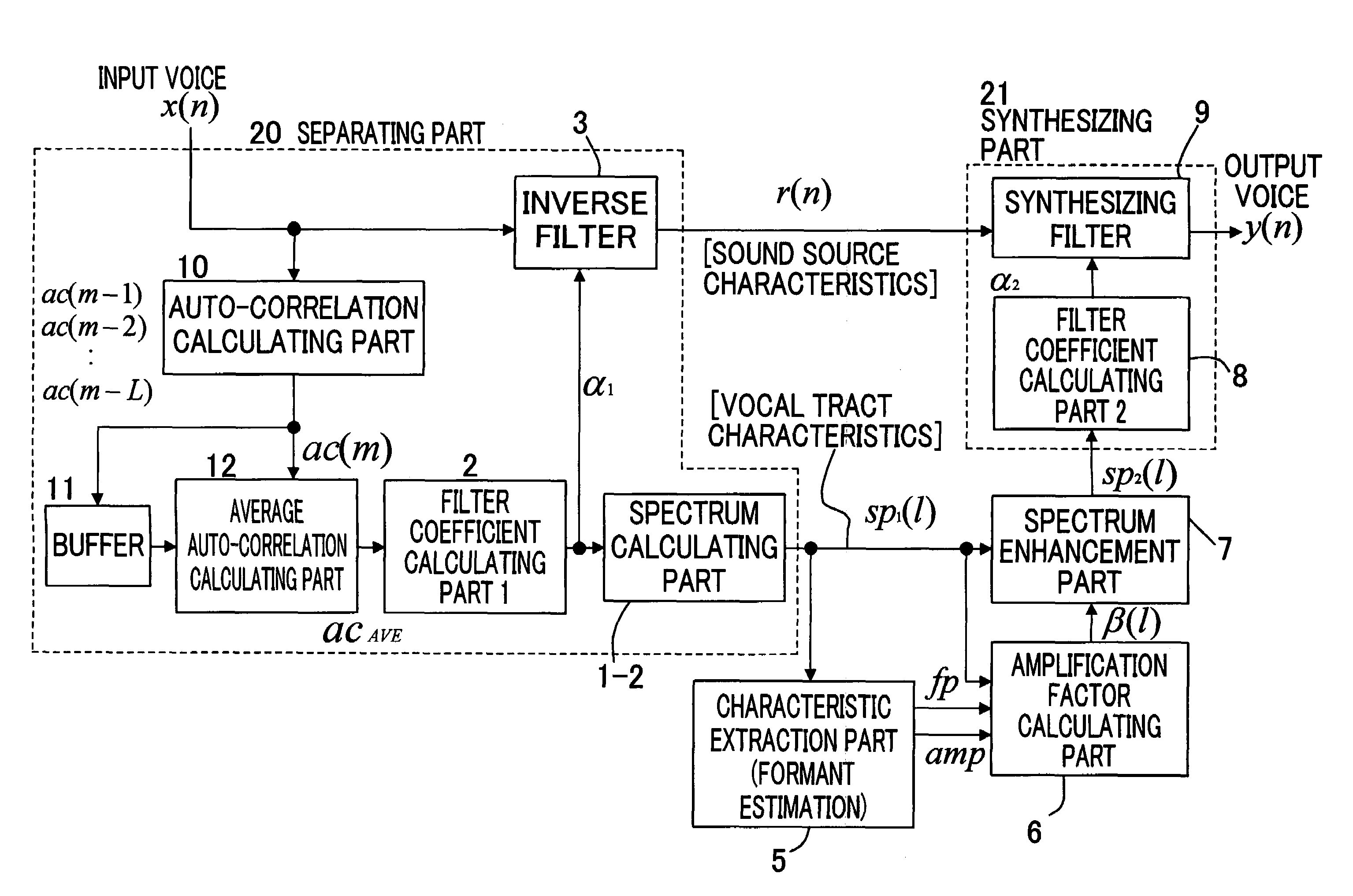
[0068]FIG. 10 is a block diagram of the construction of a first embodiment according to the present invention.

[0069]In this figure, the pitch enhancement part 4 is omitted (compared to the principle diagram shown in FIG. 9).

[0070]Furthermore, in regard to the embodied construction of the separating part 20, the average spectrum calculating part 1 inside the separating part 29 is split between the front and back of the filter coefficient calculating part 2; in the pre-stage of the filter coefficient calculating part 2, the input voice signal x(n), (0≦n10; here, the self-correlation function ac (m) (i), (0≦i≦p1) of the current frame is determined by part of Equation (1). Here, N is the frame length. Furthermore, m is the frame number of the current frame, and p1 is the order number of the inverse filter described later.

[0071]ac⁡(m)⁢(i)=∑n=iN-1⁢x(n)·x(n-i),(0≤i≤p1)(1)

[0072]Furthermore, in the separating part 20, the self-correlation function ac(m−j) (i), (1≦j≦L, 0≦i≦p1) in the immediat...

second embodiment

[0107]Accordingly, in this second embodiment, the input voice of the current frame is subjected to an LPC analysis by part of an LPC analysis part 13, and the LPC coefficients α1(i), (1≦i≦p1) that are thus obtained are used as the coefficients of the inverse filter 3.

[0108]The spectrum sp1(l) is determined from the LPC coefficients α1(i) by the second spectrum calculating part 1-2B. The method used to calculate the spectrum sp1(l) is the same as that of Equation (4) in the first embodiment.

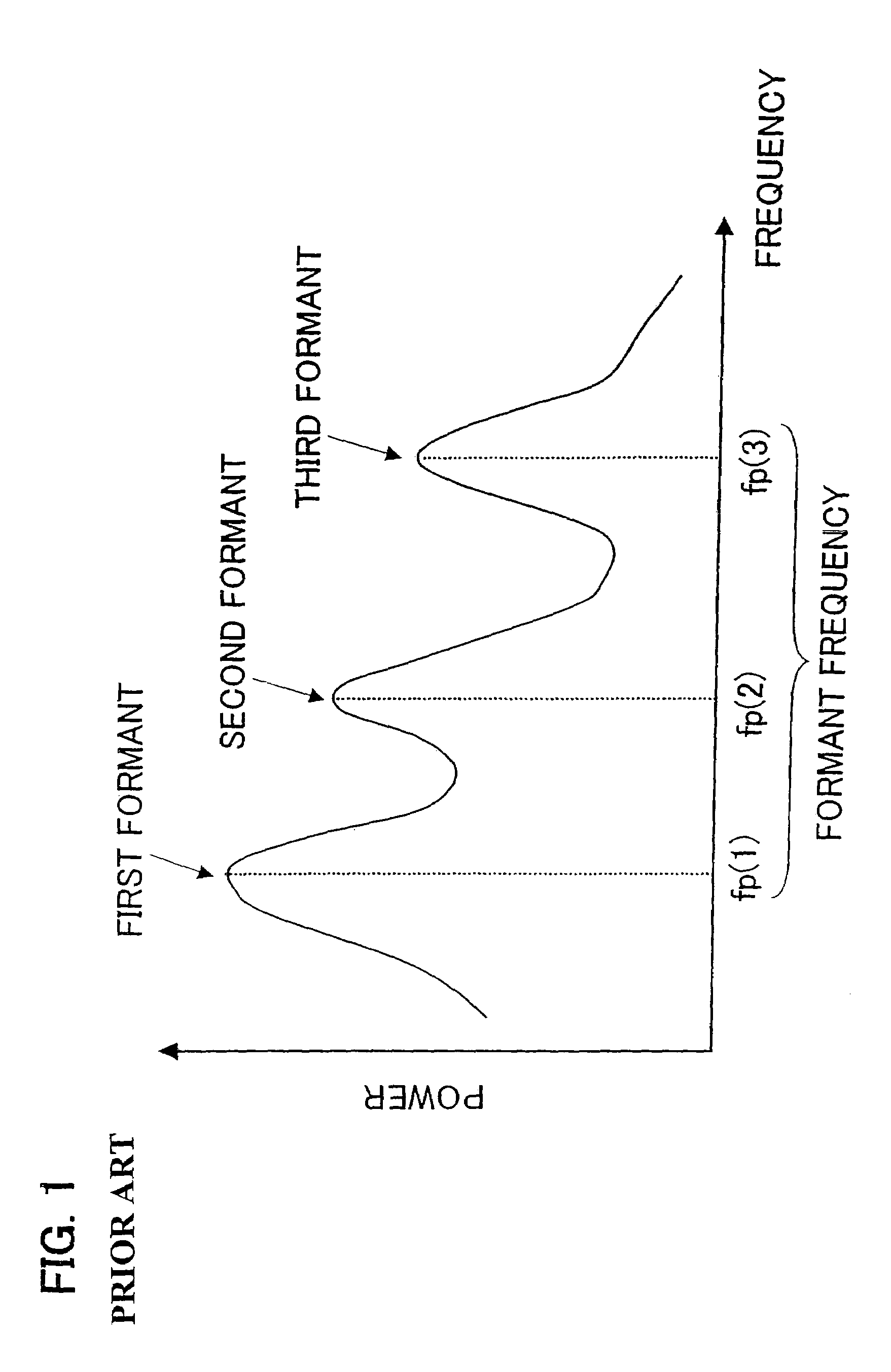
[0109]Next, the average spectrum is determined by the first spectrum calculating part, and the formant frequencies fp(k) and formant amplitudes amp(k) are determined in the formant estimating part 5 from this average spectrum.

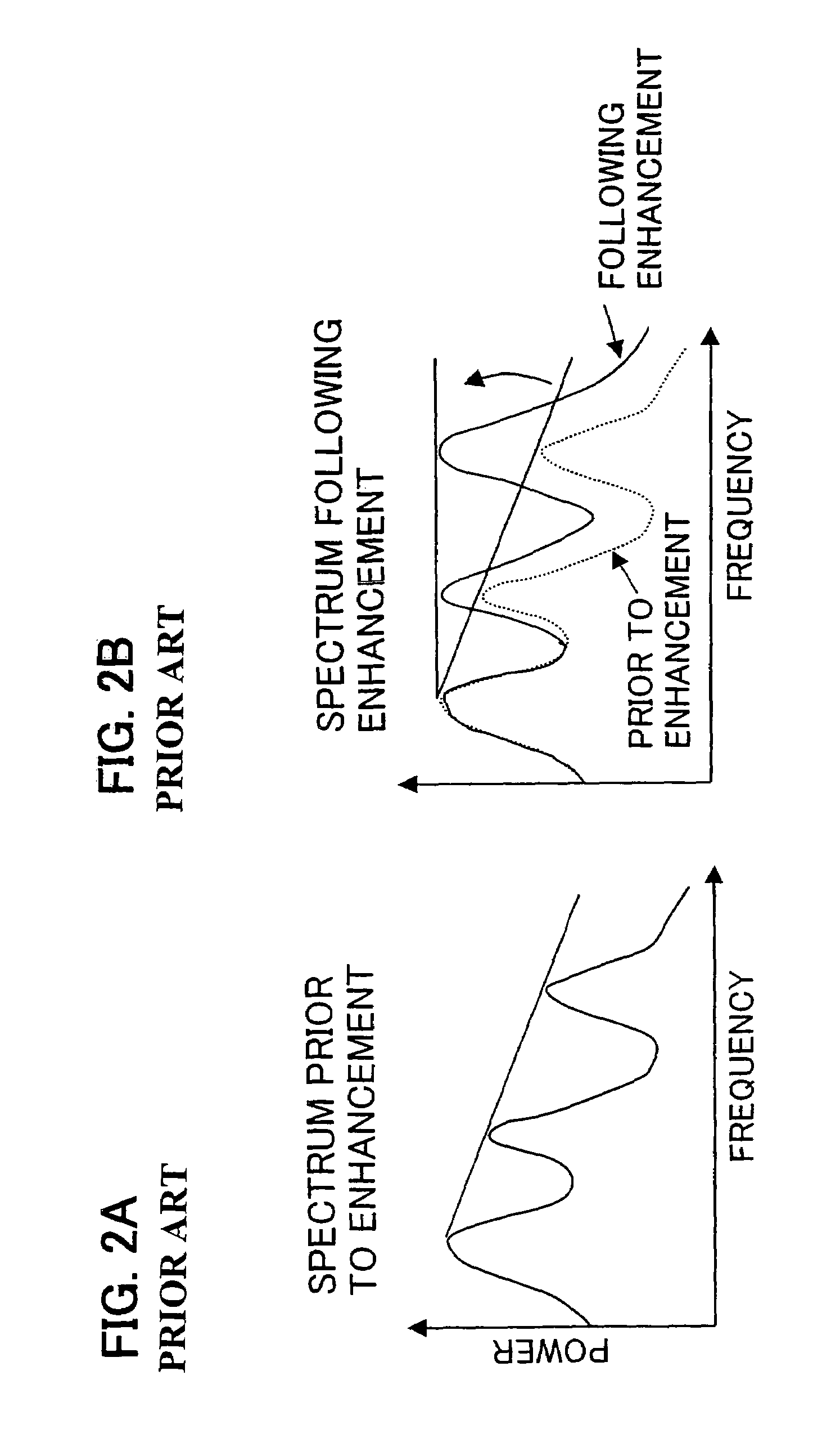
[0110]Next, as in the previous embodiment, the amplification rate β(l) is determined by the amplification rate calculating part 6 from the spectrum sp1(l), formant frequencies fp(k) and formant amplitudes amp(k), and spectrum emphasis is performed by the spectrum emphasizing ...

fourth embodiment

[0120]FIG. 16 shows a block diagram of the present invention. This embodiment differs from the first embodiment in that pitch emphasis processing is applied to the residual difference signal r(n) constituting the output of the reverse filter 3 in accordance with the principle diagram shown in FIG. 9; in all other respects, this construction is the same as the first embodiment.

[0121]The method of pitch emphasis performed by the pitch emphasizing filter 4 is arbitrary; for example, a pitch coefficient calculating part 4-1 can be installed, and the following method can be used.

[0122]First, the self-correlation rscor(i) of the residual difference signal of the current frame is determined by Equation (17), and the pitch lag T at which the self-correlation rscor(i) shows a maximum value is determined. Here, Lagmin and Lagmax are respectively the lower limit and upper limit of the pitch lag.

[0123]rscor⁡(i)=∑n=iN-1⁢r⁡(n)·r⁡(n-i),(Lagmin≤i≤Lagmax)(17)

[0124]Next, pitch prediction coefficients...


PUM


Abstract

A voice intensifier capable of reducing abrupt changes in the amplification factor between frames and realizing excellent sound quality with less noise feeling by dividing input voices into the sound source characteristic and the vocal tract characteristic, so as to individually intensify the sound source characteristic and the vocal tract characteristic and then synthesize them before being output. The voice intensifier comprises a signal separation unit for separating the input sound signal into the sound source characteristic and the vocal tract characteristic, a characteristic extraction unit for extracting characteristic information from the vocal tract characteristic, a corrective vocal tract characteristic calculation unit for obtaining vocal tract characteristic correction information from the vocal tract characteristic and the characteristic information, a vocal tract characteristic correction unit for correcting the vocal tract characteristic by using the vocal tract characteristic correction information, and a signal synthesizing means for synthesizing the corrective vocal tract characteristic from the vocal tract characteristic correction unit and the sound source characteristic, so that the sound synthesized by the signal synthesizing means is output.

Description

CROSS-REFERENCE TO RELATED APPLICATION[0001]This application is a continuation of International Application PCT / JP2002 / 011332 was filed on Oct. 31, 2002, the contents of which are herein wholly incorporated by reference.BACKGROUND OF THE INVENTION[0002]The present invention relates to a voice enhancement device which makes the received voice in a portable telephone or the like easier to hear in an environment in which there is ambient background noise.[0003]In recent years, portable telephones have becomes popular, and such portable telephones are now used in various locations. Portable telephones are commonly used not only in quiet locations, but also in noisy environments with ambient noise such as airports and [train] station platforms. Accordingly, the problem of the received voice of portable telephones becoming difficult to hear as a result of ambient noise arises.[0004]The simplest method of making the received voice easier to hear in a noisy environment is to increase the re...

Claims


Application Information

Patent Timeline
Patent Type & Authority Patents(United States)
IPC IPC(8): G10L13/02G10L21/007
CPCG10L21/0364G10L19/06
Inventor SUZUKI, MASANAOTANAKA, MASAKIYOOTA, YASUJITSUCHINAGA, YOSHITERU
Owner FUJITSU CONNECTED TECH LTD
Why Eureka
Try Eureka