
Refrigerator air control baffle assembly with sound dampening

a technology of air control device and refrigerator, which is applied in the direction of ventilation system, heating type, domestic cooling apparatus, etc., can solve the problems of adversely affecting the coil, achieve the effect of reducing in-line thickness and noise dampening, reducing ice accumulation, and consuming less energy

Inactive Publication Date: 2006-12-26
ARMOR MAGNETIC COMPONENTS
View PDF8 Cites 14 Cited by
  • Summary
  • Abstract
  • Description
  • Claims
  • Application Information

AI Technical Summary

Benefits of technology

[0021]In accordance with the present invention, a baffle assembly for an air control device is provided that eliminates the accumulation of ice while consuming less energy as compared to the prior art. In addition, an air control device is provided having a reduced in-line thickness and noise dampening features that allow it to be placed in the side-walls of refrigerators and near the door.
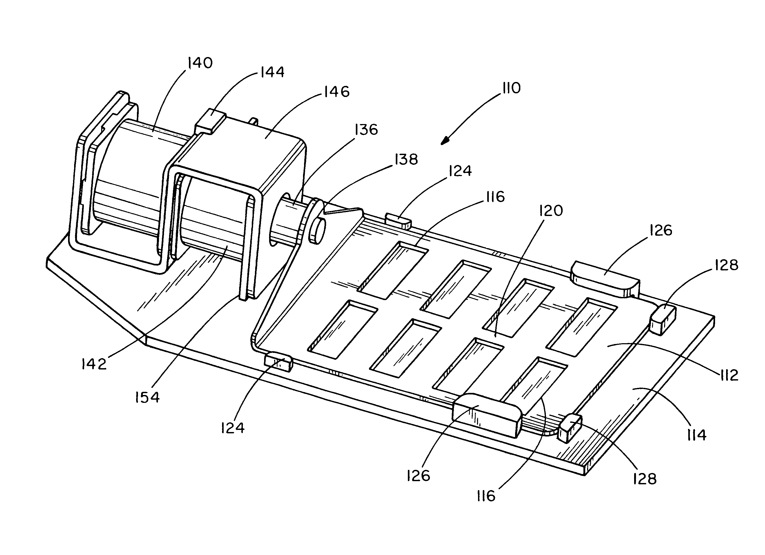
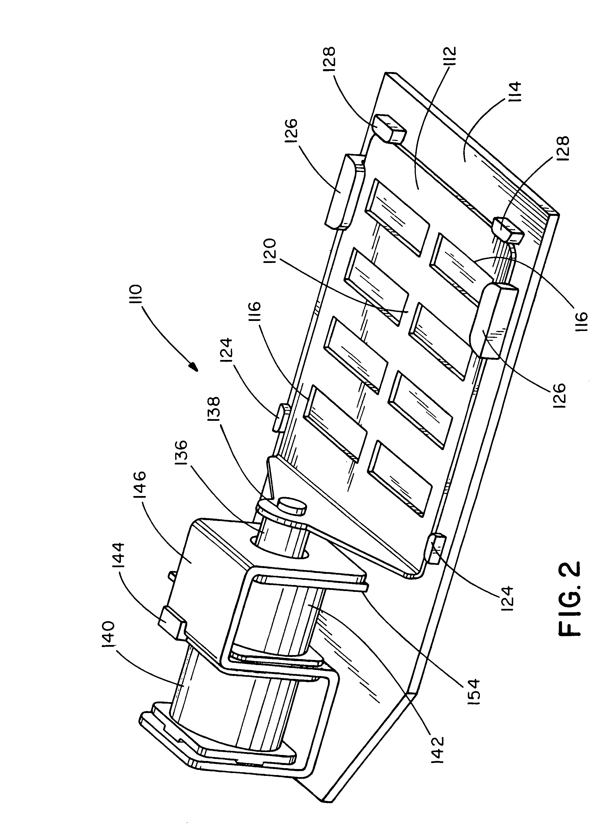
[0022]The baffle assembly includes one or two solenoid coils attached to a fixed plate, or mounted in a frame that is attached to a fixed plate. To support the magnetic fields generated by the solenoid coils, it is preferable for the frame to be constructed of a magnetic material. An armature, located inside the solenoid coil or coils, is connected to a movable plate. The movable plate rests on top of the fixed plate. When a solenoid coil is energized, the armature moves through the cavity created by the solenoid coil or coils, thereby sliding the movable plate relative to the fixed plate. Both plates have one or more apertures arranged such that in one position, portions of one of the plates covers the apertures of the other plate and in another position, the apertures on the plates align or are unobstructed. Depending on the position of the movable plate relative to the fixed plate, chilled air can enter, or is prevented from entering, the fresh food compartment of a refrigerator.
[0024]One or more temperature sensors are located in the fresh food compartment and are electronically connected to the solenoid coils. When a temperature sensor detects an air temperature at or above a preset maximum or at or below a preset minimum, the appropriate solenoid coil is energized to move the movable plate into an open or closed position, respectively. When the temperature has stopped rising or falling, the temperature sensor sends a signal that deenergizes the solenoid coil. The solenoid coils are thus only energized long enough to insure that the baffle assembly has been opened or closed, which also ensures that the plates have been freed of any ice buildup. The use of heat dissipated from the solenoid coils to melt the ice provides an energy savings over the prior art.
[0027]According to yet another aspect of the invention, when the baffle assembly is in the closed position, the movable plate is optionally held slightly open. During extended periods when the door to the fresh food compartment of the refrigerator is kept closed, such as at night, keeping the movable plate in a slightly opened position allows the fresh food compartment to maintain a desired temperature for a longer period of time, without requiring the refrigeration unit to generate more chilled air. By reducing the frequency the compressor in the refrigeration unit is activated, the refrigerator uses less energy.
[0028]In yet another aspect of the invention, the fixed plate has one or more sets of apertures located on opposite ends of the fixed plate, with the solenoid coil or coils attached to the fixed plate between the two sets of apertures. Two movable plates are attached to opposite ends of the armature. Movement of the armature causes the movable plates to move in unison resulting in all the apertures being either blocked or unobstructed. This allows more air to flow into the fresh food compartment while employing only one armature and one set of solenoid coils.
[0030]In another aspect of the invention, noise dampening features are added to curtail the amount of noise produced by the air control device when operated.

Problems solved by technology

Normally, heat generated in this way is contained within the solenoid coil, adversely affecting the coil.

Method used


Image

  • Refrigerator air control baffle assembly with sound dampening
  • Refrigerator air control baffle assembly with sound dampening
  • Refrigerator air control baffle assembly with sound dampening

Examples


Embodiment Construction

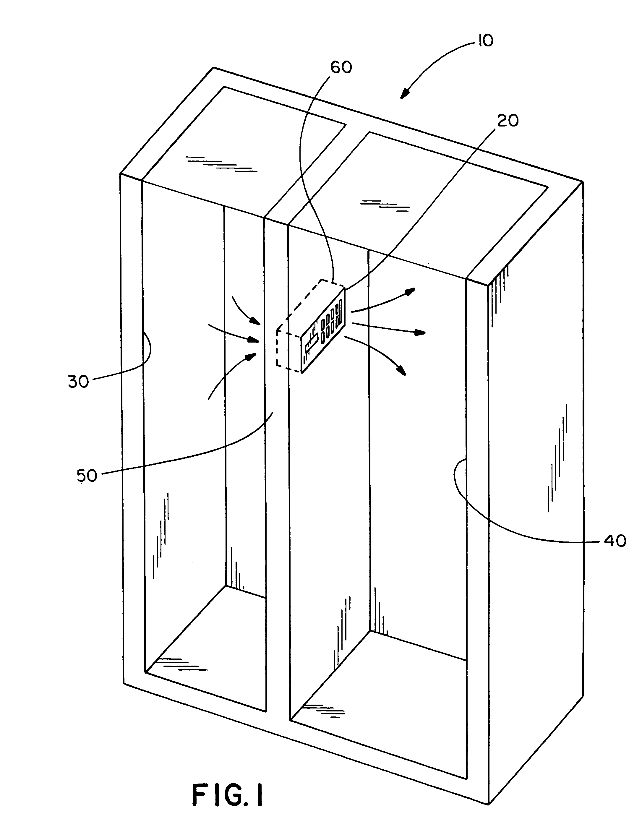
[0047]The following disclosure of the preferred embodiments is illustrative of the broad inventive concepts comprehended by the invention. One embodiment of the present invention is illustrated in FIG. 1. The invention is shown as employed in a conventional dual-compartment refrigerator 10, which contains two primary compartments. A dividing wall 50 separates a freezer compartment 30 and a fresh food compartment 40. The refrigerator 10 maintains an air temperature below freezing inside the freezer compartment 30 while the air temperature in the fresh food compartment 40 is maintained at a temperature above freezing and below a pre-set maximum. The compartments are connected by one or more air passages 60. Chilled air flows through the air passages 60 from the freezer compartment 30 to the fresh food compartment 40. The flow of the chilled air is regulated by an air control device 20 located in each of the air passages 60.

[0048]Air passages 60 may also connect the freezer compartment...


PUM


Abstract

A baffle assembly for an air control device that reduces the noise associated with operation of solenoid coils. The invention employs one or two solenoid coils mounted in a frame and attached to a fixed plate. An armature, located inside the solenoid coils, is connected on opposite ends to two movable plates which rest on top of the fixed plate. Energizing a solenoid coil moves the armature, which moves the movable plates relative to the fixed plate. Apertures in the plates are provided to control air flow through the plates. The assembly includes sound dampeners to impede the movable plates from making contact with the frame, thereby reducing the amount of noise associated with operation of the solenoid coils.

Description

RELATED APPLICATIONS[0001]This application is a continuation-in-part of application Ser. No. 10 / 449,434 filed on May 30, 2003 now U.S. Pat. No. 6,769,263.FIELD OF THE INVENTION[0002]This invention relates generally to a baffle assembly in an air control device for a refrigerator, and more particularly to an improved double baffle assembly with sound dampening characteristics,BACKGROUND OF THE INVENTION[0003]In conventional dual-compartment refrigerators, a single evaporator fan introduces chilled air into the freezer compartment by blowing air across the evaporator coils of the refrigeration unit. Chilled air is introduced into the fresh food compartment through one or more air passages in a divider wall between the two compartments. An air control device is located within one or more of the air passages to control the flow of chilled air into the fresh food compartment.[0004]Air control devices typically employ a baffle assembly having a fixed plate and a moveable plate which can s...

Claims


Application Information

Patent Timeline
IPC IPC(8): F25D17/04F25D21/00F16K31/06
CPCF16K31/06F25D17/045F25D2400/06
Inventor ARMOUR, JOHNNGUYEN, MINH
Owner ARMOR MAGNETIC COMPONENTS
Learn More