Parallel seismic depth testing using a cone penetrometer

a penetrometer and parallel seismic technology, applied in the field of parallel seismic depth testing using a cone penetrometer, can solve the problems of time-consuming and expensive parallel seismic testing

Inactive Publication Date: 2006-12-26
SLAUGHTER SCOTT H +1
View PDF7 Cites 7 Cited by
  • Summary
  • Abstract
  • Description
  • Claims
  • Application Information

AI Technical Summary

Problems solved by technology

Parallel seismic testing is expensive and time consuming because the borehole must be drilled and cased (or at least braced in the case of a geophone receiver).

Method used


Image

  • Parallel seismic depth testing using a cone penetrometer
  • Parallel seismic depth testing using a cone penetrometer
  • Parallel seismic depth testing using a cone penetrometer

Examples


Embodiment Construction

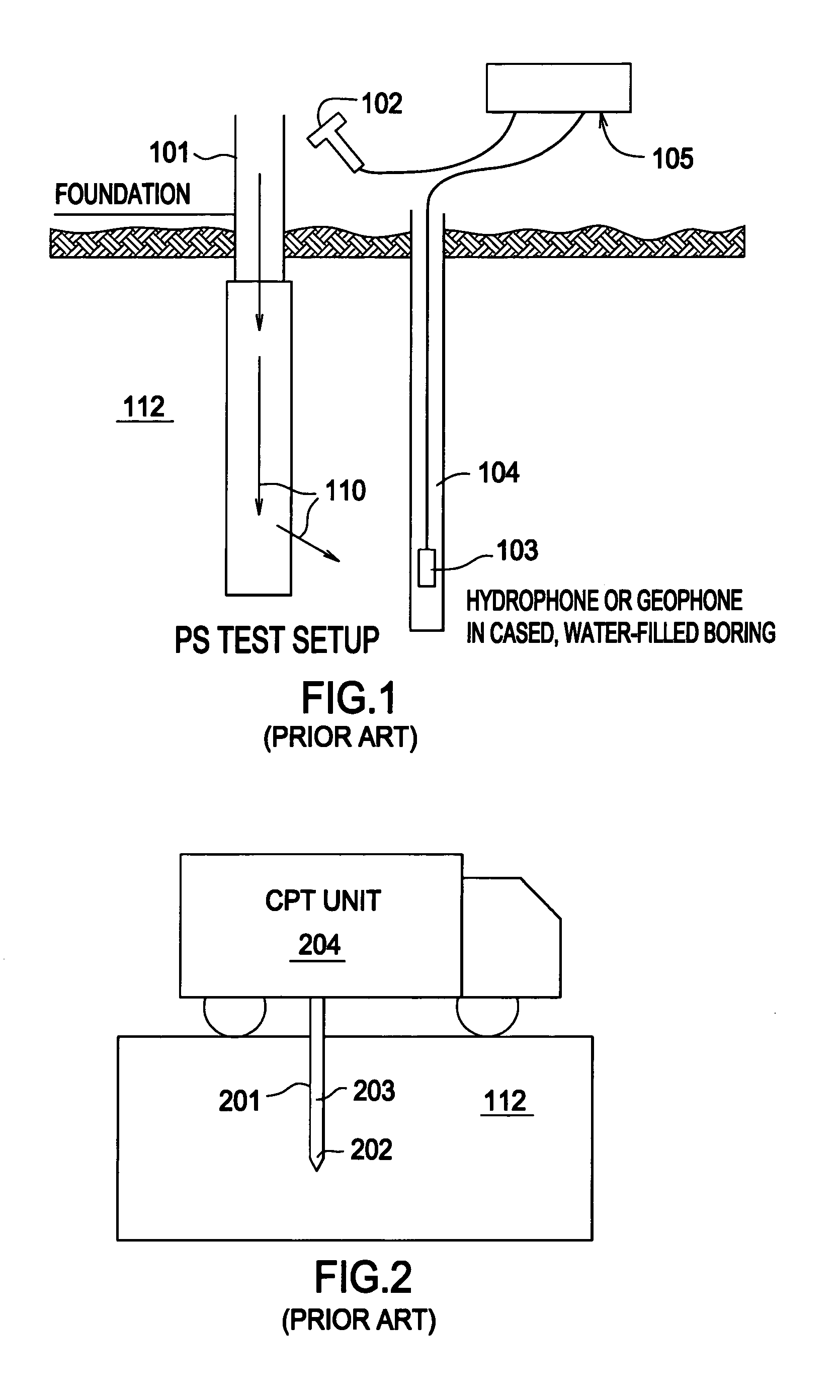
[0020]FIG. 1 (prior art) is a side schematic view of a conventional parallel seismic testing device. Foundation 101 (or some element connected to the top of the foundation, such as a pile cap) is impacted by impactor 102 (a hammer or the like). Impact hammer 102 is typically an instrumented three pound hammer producing 2000–5000 pounds of force. The instruments record (among other things) the impact time (T0) of the impactor, so that the propagation time of waves 110 can be measured. An alternative hammer 102 might comprise a steel sledge hammer, three to eight pounds, with an accelerometer mounted next to the impact location to record the impact time.

[0021]Compressional, shear, or flexural waves 110 travel down through foundation 101 and are transmitted into the surrounding soil 112. Borehole 104 is drilled out and the drill bit removed. Borehole 104 may be cased or braced. Receiver 103 is lowered into borehole 104. Borehole 104 must be cased if receiver 103 is a hydrophone, becaus...


PUM


Abstract

A parallel seismic tester utilizing a cone penetrometer to test the depth of a foundation or the like comprises three important elements: the cone penetrometer which houses a receiver, an impactor to impact the structure, and data gathering and analyzing equipment. The receiver may comprise a hydrophone, a geophone, or accelerometers. In the case where the receiver is a hydrophone, the hydrophone is embedded in a plastic, water filled container within the cone penetrometer head, and the head retracts prior to running tests.

Description

BACKGROUND OF THE INVENTION[0001]1. Field of the Invention[0002]The present invention relates to apparatus and methods for testing the depth of structures such as foundations using parallel seismic testing with a cone penetrometer to house the receiving element.[0003]2. Description of the Prior Art[0004]Parallel Seismic (PS) testing has been employed for such uses as determining the depth of an unknown foundation when the foundation top is not accessible or when the piles are too long and slender to be tested by echo techniques. Typically a borehole is drilled into the soil adjacent to the foundation, and the borehole is cased. In the case where the receiver is a hydrophone, the cased borehole is filled with water. In the case where the receiver is a geophone, several geophone receiver components are spaced apart in the borehole.[0005]An exposed portion of the foundation is then impacted with a hammer or the like, and compression or flexural waves travel down the foundation and are ...

Claims


Application Information

Patent Timeline
Patent Type & Authority Patents(United States)
IPC IPC(8): E21B47/04G01B17/00E02D1/02E02D23/00G01V1/00
CPCE02D1/022E02D23/00G01V1/003
Inventor SLAUGHTER, SCOTT H.OLSON, LARRY
Owner SLAUGHTER SCOTT H
Why Eureka
Try Eureka