Method for operating a well jet device during cleaning of the downhole area of a formation and device for carrying out said method

a well-jet device and downhole area technology, applied in the field of pumping devices, can solve the problems of not providing for the possibility of selectively cleaning the downhole area of a formation, not providing for the possibility of installing various functional inserts, not enabling to utilize capacity, etc., to achieve the most efficient ultrasonic treatment of a producing formation, increase the permeability of non-working, and increase the reliability and productivity of the device.

Inactive Publication Date: 2006-12-26
KHOMYNETS ZINOVIY DMITRIEVICH
View PDF1 Cites 10 Cited by
  • Summary
  • Abstract
  • Description
  • Claims
  • Application Information

AI Technical Summary

Benefits of technology

[0010]The objective to be achieved through this invention is to raise the reliability and productivity of the well jet device when treating a producing formation owing to identifying non-working or poorly working layers of such a producing formation and exactly acting on the downhole area for restoring its permeability and removing mudding particles from the well, which foul the downhole area, as well as for optimizing the dimensions of various components of the device.
[0013]An analysis of the operation of the well jet device has shown that the reliability and the productivity of the device may be increased by optimizing the succession of the actions performed during cleaning of the near-borehole area of the formation in wells, in particular during performing works with treatment of the formation ultrasonically as well as in the result of making various components of the device under strictly defined dimensions.
[0016]Thus, the set objective has been achieved—to raise the reliability and the productivity of the well jet device while treating the producing formation—owing to identifying non-working and poorly working layers of the producing formation and exactly acting on the downhole area with the restoration of its permeability and removal of mudding particles, which foul the downhole area, our of the well, as well as owing to the optimization of the dimensions of various components of the device.

Problems solved by technology

But, the said method does not provide for a possibility of selectively acting on the downhole area of a formation.
Furthermore, the said device does not provide for a possibility of installing various functional inserts, what, in a number of cases, narrows the field of application of the said method of operation and the said device.
However, the said method of operation and the said well jet device do not enable to utilize the capacity of the well jet device in full, which is due to a limited number of operations for treating a formation, primarily with the use of chemically active liquid media, and to the lack of the possibility to exactly act on non-working or poorly working layers of a producing formation, as well as to non-optimal relations between the dimensions of the components of the well jet device.

Method used


Image

  • Method for operating a well jet device during cleaning of the downhole area of a formation and device for carrying out said method
  • Method for operating a well jet device during cleaning of the downhole area of a formation and device for carrying out said method
  • Method for operating a well jet device during cleaning of the downhole area of a formation and device for carrying out said method

Examples


Embodiment Construction

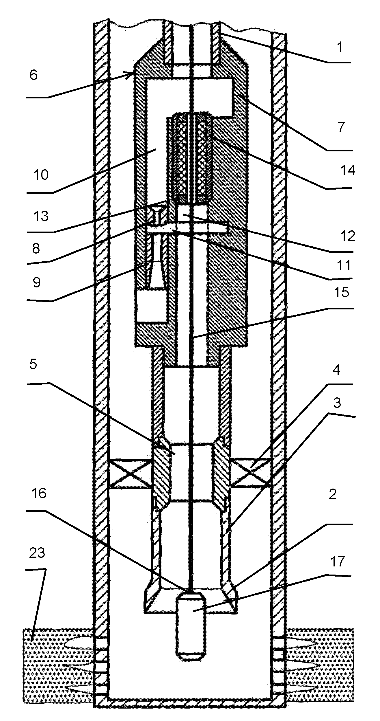
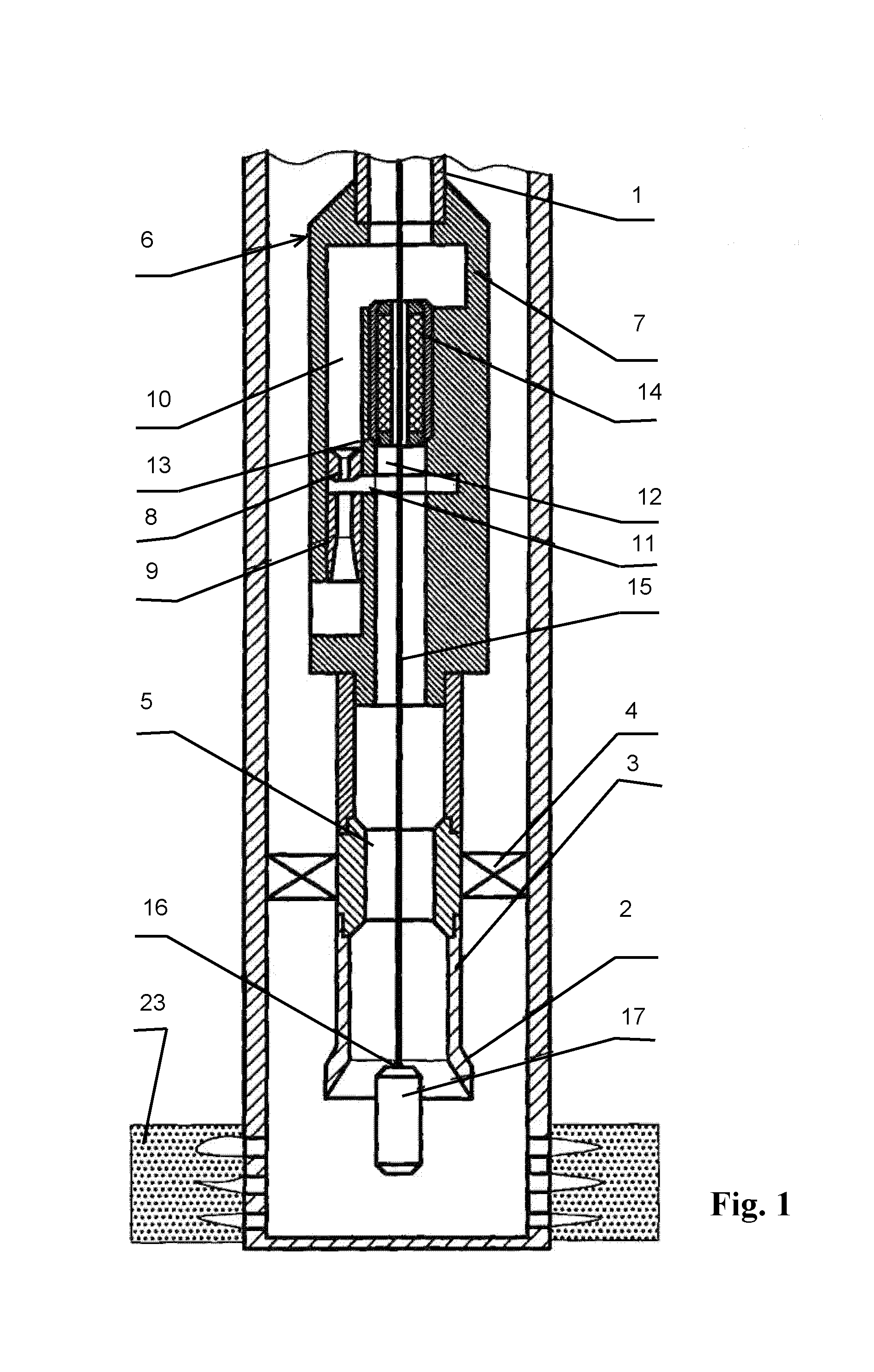
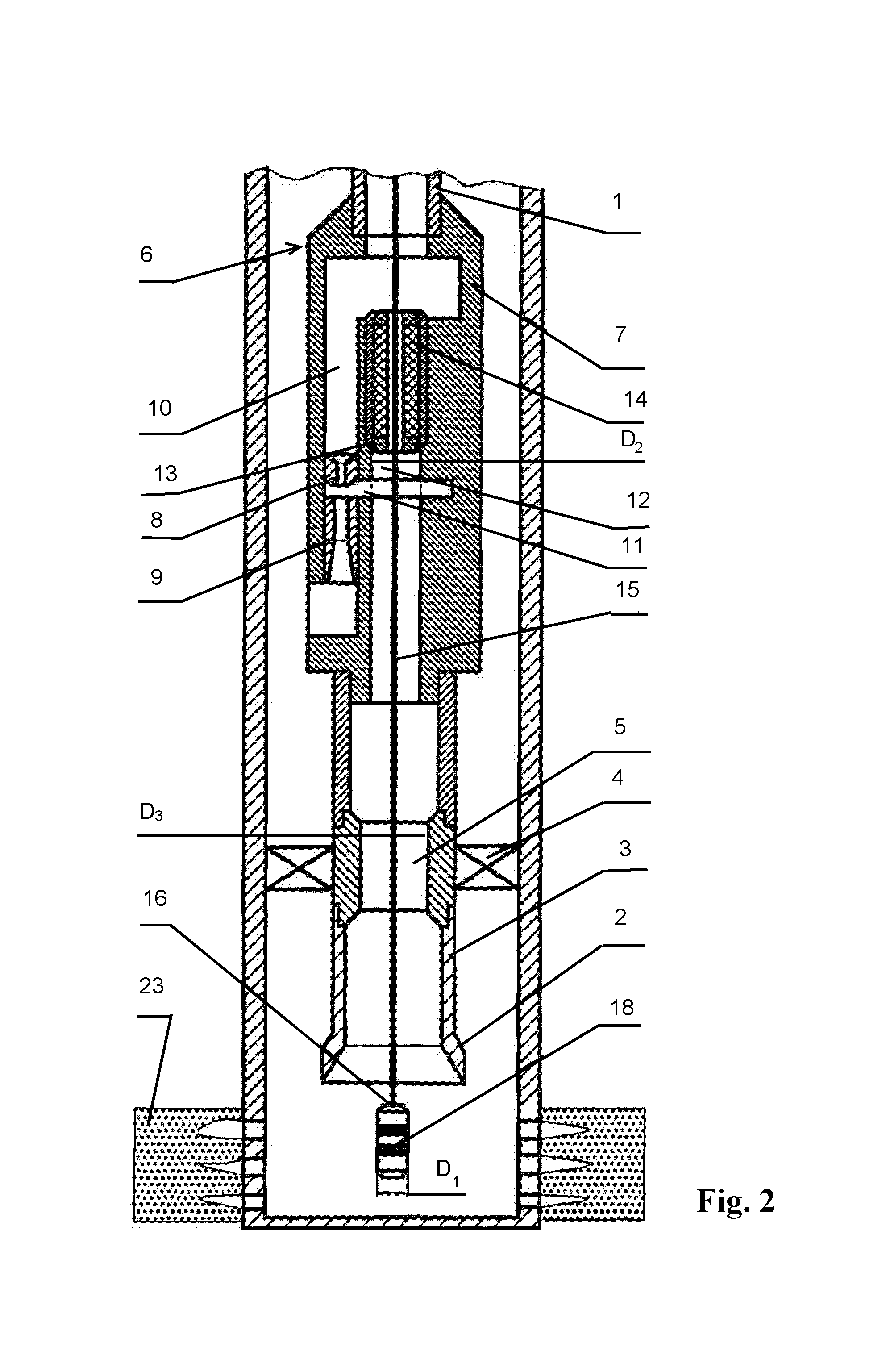
[0020]The well jet device comprises, mounted bottom up on the tubing string 1, the input cone 2 with the shank 3, the packer 4 with the central passage 5 made therein and the jet pump 6, in the case 7 of which the active nozzle 8 and the mixing chamber 9 are coaxially installed as well as the passage 10 for supplying an active medium, the passage 11 for supplying a medium pumped out of the well and the stepped through passage 12 with the mounting seat 13 between the steps are made, the possibility being provided for installing the sealing assembly 14, which is arranged movably on the logging cable or the wire 15 above the tip 16 for connecting the receiver-transformer of physical fields 17, the instrument 18 for ultrasonic action on the formation, and replaceable functional inserts, i.e., a depression insert and an insert for recording curves reflecting restoration of formation pressure in the under-packer area 19 of the well with the sampler 20 and the autonomous instrument 21 in t...


PUM


Abstract

The invention relates to pumping engineering, mainly to well pumping devices for extracting oil from wells. The inventive method consists in assembling from the bottom upward an input cone provided with a shank, a packer and a jet pump and in running said assembly with the aid of a tubing string into a well. Afterwards, a receiver transformer of physical fields is also run into said well, background measurements of temperature and other physical fields are carried out, a formation is drained and the work of the individual interlayer of a productive strata is evaluated. An ultrasonic action is performed on the productive strata. The hydrodynamic action being performed on the productive strata during said operation, the entire formation is exposed to the combined action of ultrasonic oscillations and a hydrodynamic effect. Afterwards, the unit for ultrasonic effect is pulled out from the well to the surface. The hydrodynamic and geophysical investigations of the well being carried out using the jet pump and replaceable functional inserts, the assembly and the jet pump are pulled out from the well to the surface and the well is prepared in order to be put into operation. The invention makes it possible to optimise the dimensions of various elements of the device, thereby increasing the operating reliability and performance of the well jet device during the treatment of the productive strata.

Description

FIELD OF THE INVENTION[0001]This invention relates to the field of pump engineering, primarily to well pump devices for extracting oil from wells.PRIOR ART[0002]Known in the art is a method of operating a well jet device, which comprises supply, via the tubing string, an active liquid medium to the nozzle of a jet device, wherein the said liquid medium entrains a passive medium and mixes with it while supplying the mixture of the media out of a well to the surface (RU 2059891 C1).[0003]Known from the same source is a well jet device, which comprises a jet pump being installed on the tubing string in a well, and a geophysical instrument being arranged in the tubing string below the said jet pump.[0004]The known method of operation and the well jet device enable to pump out of a well various extracted media, e.g., oil, with the simultaneous treatment of the extracted medium and the downhole area of a formation.[0005]But, the said method does not provide for a possibility of selectivel...

Claims


Application Information

Patent Timeline
Patent Type & Authority Patents(United States)
IPC IPC(8): E21B43/16E21B43/00E21B43/12F04F5/10F04F5/46
CPCE21B43/003E21B43/124F04F5/10F04F5/464E21B28/00
Inventor KHOMYNETS, ZINOVIY DMITRIEVICH
Owner KHOMYNETS ZINOVIY DMITRIEVICH
Why Eureka
Try Eureka