Resin molding machine

a molding machine and resin technology, applied in the field of resin molding machines, can solve the problem of not being able to disclose the gazette, achieve the effect of preventing the damage of the work, improving the reliability of the machine, and reducing the amount of useless resin or scraps

Inactive Publication Date: 2006-12-26
APIC YAMADA CORP
View PDF12 Cites 9 Cited by
  • Summary
  • Abstract
  • Description
  • Claims
  • Application Information

AI Technical Summary

Benefits of technology

[0033]means for adjusting variations of thickness of the substrate may be provided to the work holding section. With this structure, the variations of the thickness of the substrate can be absorbed, so that damage of the work can be prevented and reliability of the machine can be improved.
[0034]Further, by employing the cavity plate having a vertical gate communicated to the concave groove, amount of useless resin or scraps can be reduced.

Problems solved by technology

The gazette does not disclose how to carry the cavity plate and the circuit board into the molding die, how to carry out the molded circuit board therefrom, how to remove useless resin from the molded products and how to separate the cavity plate from the molded circuit board.

Method used


Image

  • Resin molding machine
  • Resin molding machine
  • Resin molding machine

Examples


first embodiment

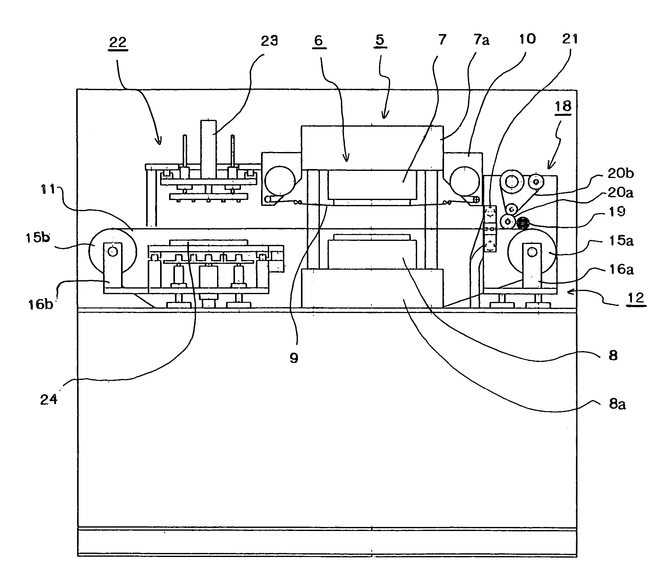
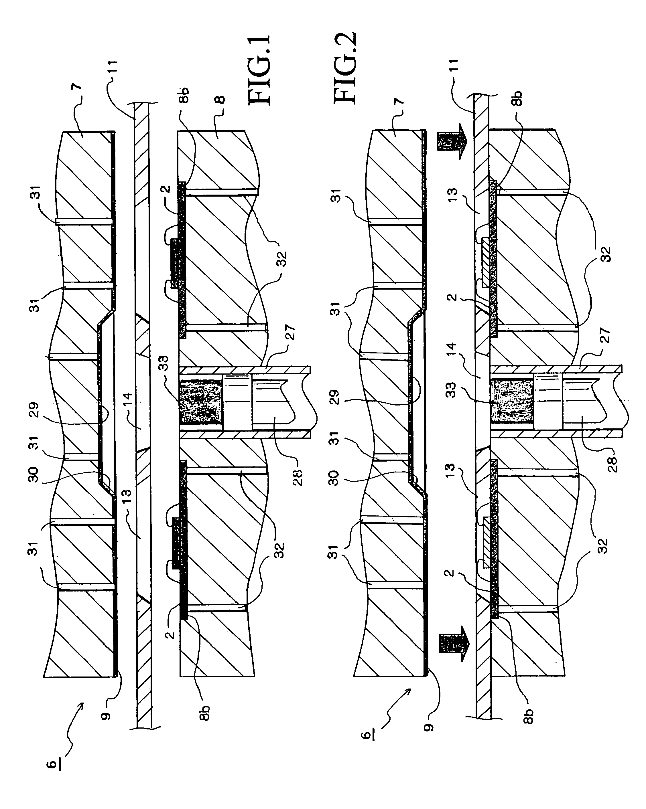
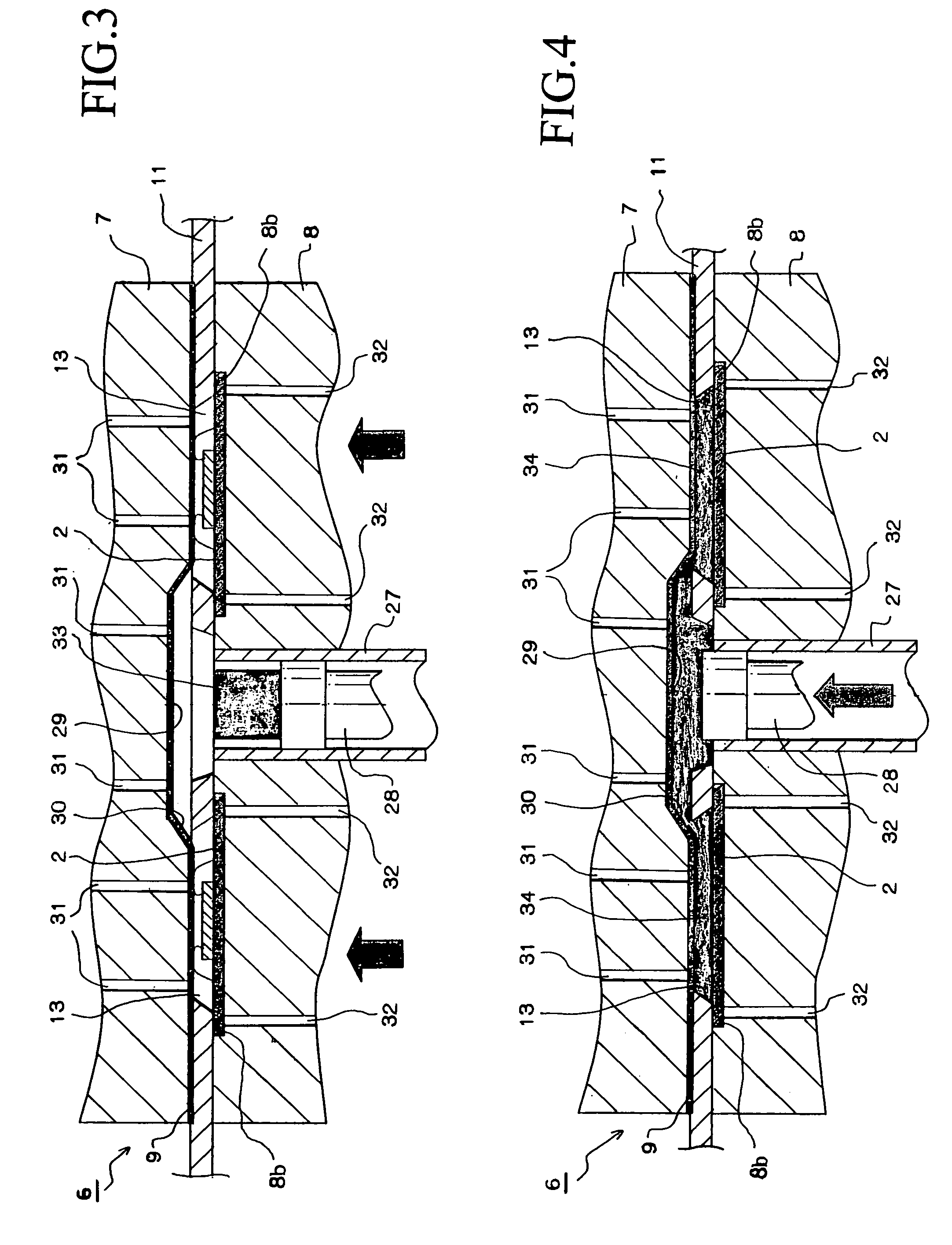
[0060]A first embodiment will be explained with reference to FIGS. 1–11B. FIGS. 1–7 are explanation views showing molding steps of a resin molding machine of the first embodiment; FIG. 8 is a front view of the resin molding machine; FIG. 9 is a plan view of the resin molding machine; FIG. 10A is a plan view of a cavity plate of the resin molding machine; FIG. 10B is a sectional view of the cavity plate; FIG. 11A is a plan view of another cavity plate; and FIG. 11B is a perspective view of the cavity plate shown in FIG. 11A.

[0061]Firstly, an outline of the resin molding machine will be explained. The resin molding machine is a transfer molding machine.

[0062]In FIGS. 8 and 9, a work feeding section 1 sends works 2 from a feeding magazine toward a loader 4. In the present embodiment, semiconductor chips are mounted on a plastic substrate of each work 2, but other types of works, e.g., lead frames on which semiconductor chips are mounted, mere substrates, may be molded by the resin mold...

second embodiment

[0094]A second embodiment will be explained with reference to FIGS. 12–16C. FIG. 12 is a plan view of a resin molding machine of the second embodiment; FIG. 13 is a front view of the resin molding machine shown in FIG. 12 seen from an arrow F; FIG. 14 is an explanation view of the resin molding machine shown in FIG. 12 seen from an arrow A; FIG. 15 is a front view of the resin molding machine shown in FIG. 13 seen from an arrow B; FIG. 16A is an explanation view of the cavity plate; FIG. 16B is an explanation view of a supporting frame; and FIG. 16C is an explanation view of a conveying arm. Note that, the structural elements explained in the first embodiment are assigned the same symbols, and explanation will be omitted. Difference will be mainly explained.

[0095]In FIG. 12, a plurality of the cavity plates 11 are circulated on the track 83, so that the cavity plates 11 can be continuously fed to the press section 5. A surface of the track 83 is parallel to the clamping face of the ...

third embodiment

[0114]A third embodiment will be explained with reference to FIGS. 17–19. The structure of the resin molding machine of the present embodiment is almost the same as that of the former embodiments, so differences will be mainly explained. The feature of the present embodiment is a compression molding die 40 provided in the press section 5. Liquid resin 47 is used as the resin material. In the present embodiment, an upper die 41 is a movable die, and a lower die 42 is a fixed die, and vice versa. The structural elements explained in the former embodiments are assigned to the same symbols, and explanation will be omitted.

[0115]In FIG. 17, cuts and resin paths are not shown in a clamping face of the upper die 41. Overflow cavities 43, which are capable of communicating to the cavity holes 13, are formed in the clamping face of the upper die 41. Air sucking holes 44, which are communicated to an air sucking unit (not shown), are formed in the upper die 41. Some air sucking holes 44 are o...


PUM

PropertyMeasurementUnit
temperatureaaaaaaaaaa
thicknessaaaaaaaaaa
sizeaaaaaaaaaa

Abstract

The resin molding machine has a simple molding die, which can be easily maintained, and is capable of molding a work without pretreatments. The resin molding machine for molding the work with resin. The resin molding machine comprises: a press section having a molding die; a cavity plate having a cavity hole, which defines a shape and thickness of a resin mold section of the work; a mechanism for repeatedly carrying the cavity plate into and out from the press section; and a mechanism for positioning the cavity plate onto the molding die.

Description

[0001]This Nonprovisional application claims priority under 35 U.S.C. § 119(a) on Patent Application No. 2002-348420 filed in Japan on Nov. 29, 2002, the entire contents of which are hereby incorporated by reference.BACKGROUND OF THE INVENTION[0002]The present invention relates to a resin molding machine, more precisely relates to a resin molding machine, in which a work is clamped and molded with resin in a molding die.[0003]A transfer molding machine, which molds resin mold sections (package sections) of semiconductor devices with resin, has been known as an example of resin molding machines. In the transfer molding machine, works, e.g., mere substrates, plastic boards on which semiconductor chips are mounted, lead frames on which semiconductor chips are mounted, are set in a molding die having cavities and clamped by the molding die. Resin supplied in a pot is pressurized by a plunger so as to send the resin to the cavities via resin paths (runners and gates). By filling the cavi...

Claims


Application Information

Patent Timeline
Patent Type & Authority Patents(United States)
IPC IPC(8): B29C45/14H01L21/56B29C43/36B29C45/02
CPCB29C43/36B29C45/02B29C43/32B29L2031/3481B29C2043/5825H01L2924/181H01L2224/48091H01L2924/00014H01L2924/00012H01L21/56
Inventor TOFUKUJI, SHIGEYUKISAKAMOTO, TOMOO
Owner APIC YAMADA CORP
Why Eureka
Try Eureka