
Medical device with shield having a retractable needle

a technology of retractable needles and medical devices, which is applied in the direction of guide wires, catheters, applications, etc., can solve the problems of transmission of various pathogens, and achieve the effect of reducing the overall cost of the device and improving manufacturing efficiency

Inactive Publication Date: 2006-12-26
MDC INVESTMENT HLDG
View PDF57 Cites 64 Cited by
  • Summary
  • Abstract
  • Description
  • Claims
  • Application Information

AI Technical Summary

Benefits of technology

[0010]Accordingly, when configured and used as described above, the present invention provides a safe and effective method for infusing medicine, transfusing blood or plasma, or inserting a guide wire into a patient. In addition, the device is designed to improve manufacturing efficiencies thereby reducing the overall cost of the device.

Problems solved by technology

Handling of such medical devices after the needle is withdrawn from the patient can result in transmission of various pathogens, most notably human immune virus (HIV), due to in inadvertent needle stick to medical personnel.

Method used


Image

  • Medical device with shield having a retractable needle
  • Medical device with shield having a retractable needle
  • Medical device with shield having a retractable needle

Examples


first embodiment

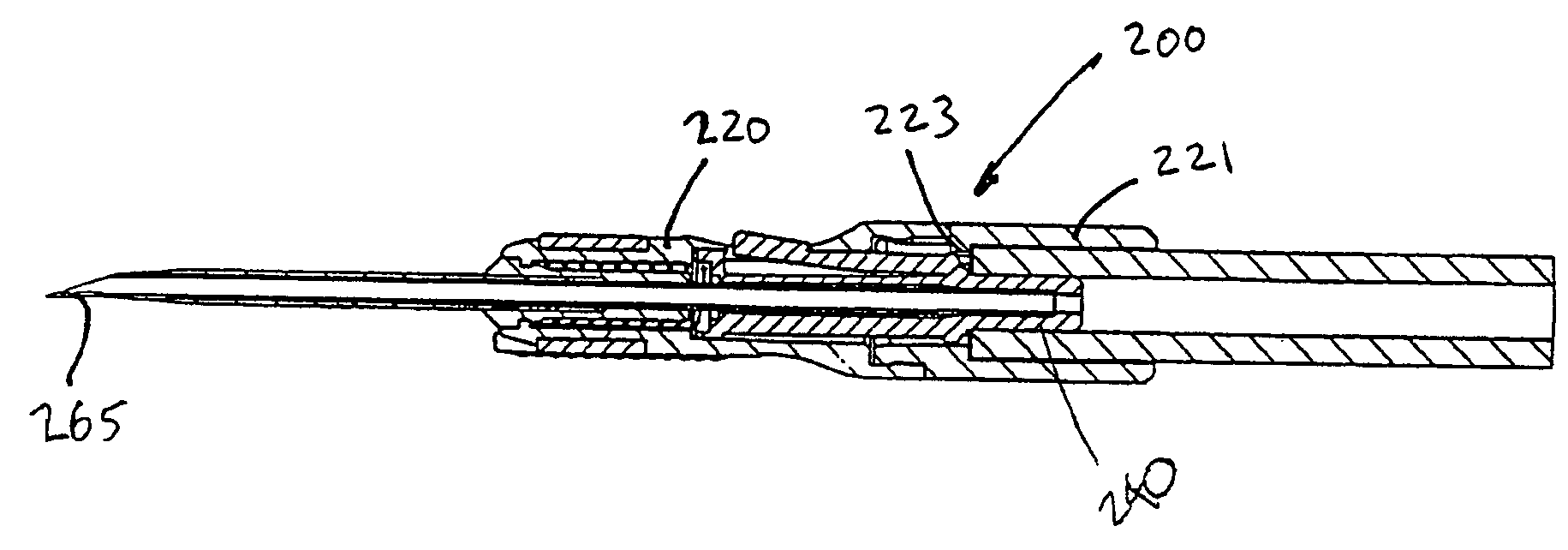
[0065]In the embodiment illustrated in FIGS. 4–9, the device is described as using a one-piece housing. It may be desirable to provide a two-piece barrel so that the needle, and needle are exposed after assembly. Such a structure is disclosed in FIGS. 10–11, in which elements similar to the elements in the first embodiment are designated with like reference numbers with the addition of 200s.

[0066]Referring to FIGS. 10–11, the device 200 includes a forward housing 220 and a rearward housing 221. During assembly, the needle hub 240 is inserted into the forward housing 220. The rearward end of the needle hub 240 projects rearwardly from the forward housing 220. Since the needle hub 240 and needle 265 are exposed, adhesive can be readily applied to bond the needle to the needle hub. The rearward housing 221 is then attached to the forward housing 220 to enclose the needle hub 240. The rearward housing 221 includes a flange 223 that cooperates with the needle retainer to limit the rearwa...

embodiment 300

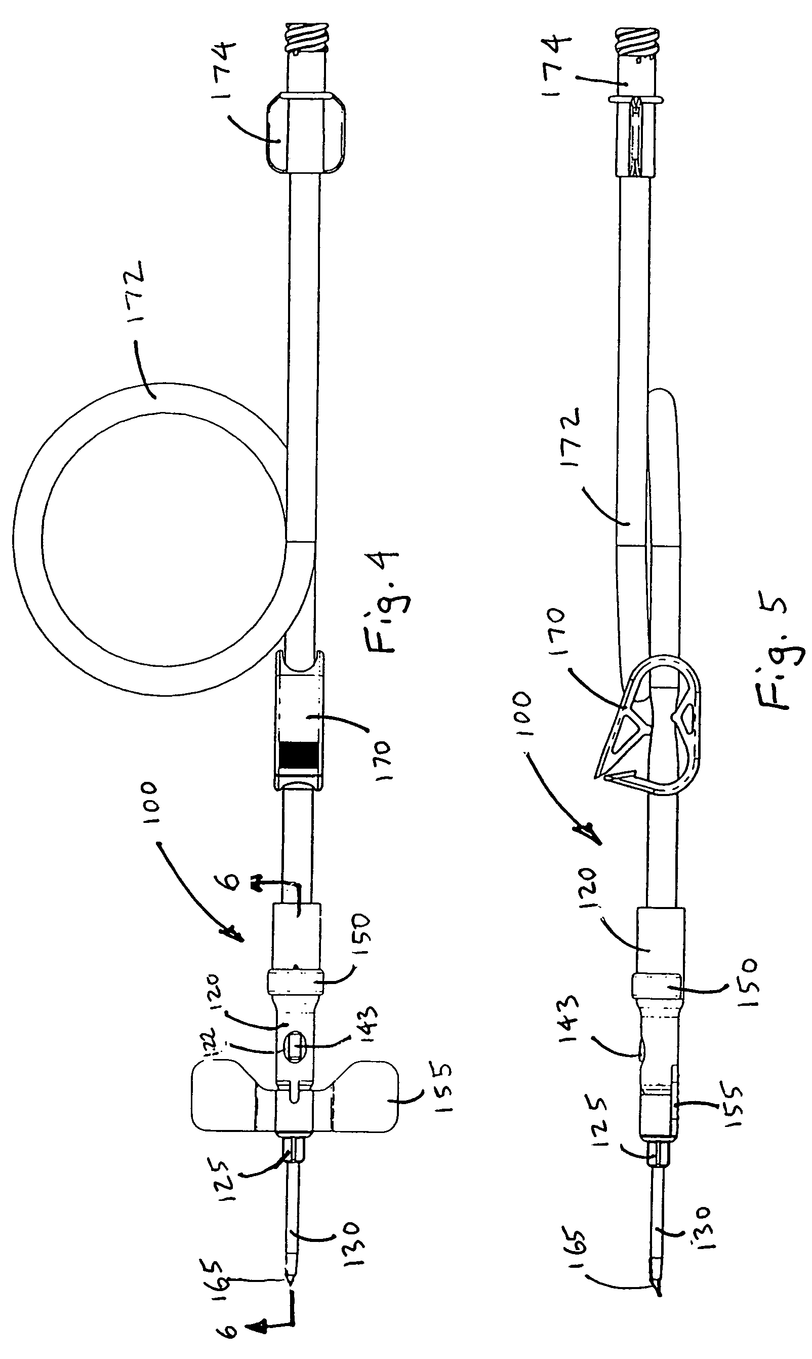
[0094]Many of the elements of the device 400 are the same or similar to the elements of embodiment 300. For instance, the device 400 includes a barrel 420, a needle 465 projecting forwardly from the barrel, a needle shield 430 sheathing the needle, a spring 460 biasing the needle rearwardly, and a needle hub 440 having a needle retainer 442 releasably retaining the needle in the projecting position against the rearward bias of the spring.

[0095]However, the barrel 420 has a cut-out or slot for receiving the Y-shaped connector hub 450 having two ports rather than the single port of the connector hub 350. The connector hub 450 has a “straight through” portion or leg that is configured similarly to the rearward portion of the connector hub 350. The straight through portion 451 is axially aligned with the barrel 420 and the needle 465. The rearward end of the “straight through” leg 451 is generally open, and forms a connector, such as a Luer connector for attaching a separate medical dev...


PUM


Abstract

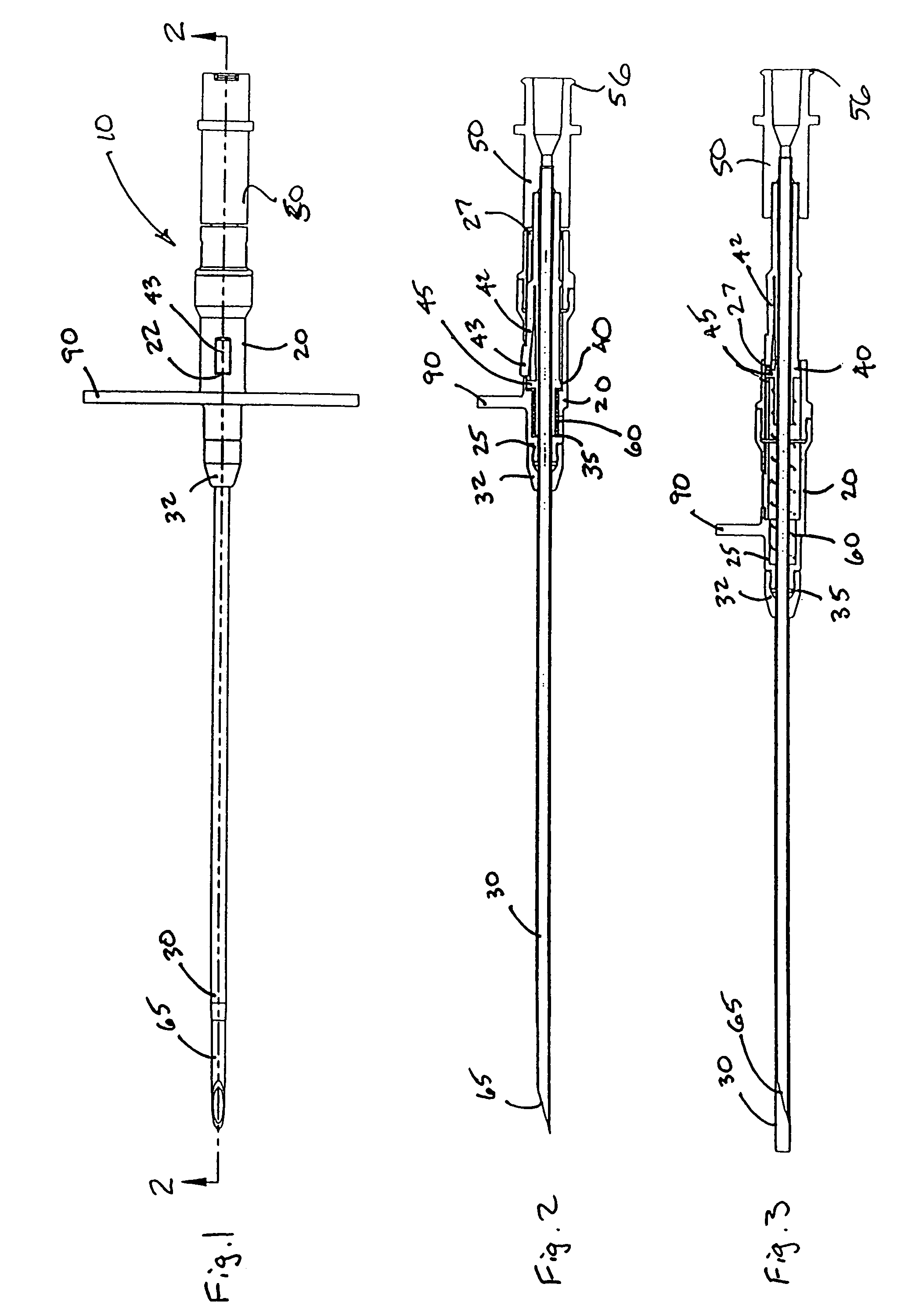
Needle-bearing medical devices are provided for fluid infusion, fluid transfusion, and inserting a guide wire. After use the needle is shielded to render the contaminated needle safe to prevent inadvertent needle sticks. The device includes a housing and a needle having a sharpened tip. A biasing element biases the needle toward a position in which the sharpened tip is shielded.

Description

RELATED APPLICATIONS[0001]This application is a continuation of U.S. application Ser. No. 09 / 837,539, filed Apr. 18, 2001, set to issue as U.S. Pat. No. 6,786,875 on Sep. 7, 2004, which is a continuation-in-part of U.S. application Ser. No. 09 / 628,180, filed on Jul. 28, 2000, which issued as U.S. Pat. No. 6,398,743 on Jun. 4, 2002. This application also claims priority to U.S. Provisional Application No. 60 / 198,032, filed Apr. 18, 2000 and U.S. Provisional Application No. 60 / 223,651 filed Aug. 7, 2000. Each of the foregoing applications is hereby incorporated herein by reference.FIELD OF INVENTION[0002]The present invention relates to medical devices for fluid infusion, fluid transfusion, and inserting a guide wire into a patient. In a particular, the present invention relates to medical devices having a sharpened needle used for introducing a guide wire into a patient. The needle pierces the patient to provide vascular access, and the guide wire is then inserted into the patient th...

Claims


Application Information

Patent Timeline
Patent Type & Authority Patents(United States)
IPC IPC(8): A61B5/00A61M5/178B65D81/00A61B5/153A61B5/15A61M5/32A61M25/00A61M25/06A61M25/08A61M25/09
CPCA61M25/0631A61M25/0637A61M25/0643A61M25/09041A61B5/1411A61M5/3257A61B5/15003A61B5/150389A61B5/150503A61B5/150656A61B5/15074A61B5/1535
Inventor BARKER, JOHN M.HALSETH, THOR R.BOTICH, MICHAEL J.
Owner MDC INVESTMENT HLDG
Learn More