Catalyst regenerator with a centerwell

a catalyst and centerwell technology, applied in the field of catalyst recovery, can solve the problems of difficult processing and/or disposal of slurry oil from the quench tower, difficult removal of catalyst fines, and significant differences between the light olefin fcc process and the conventional fcc operation of the quench tower, and achieve the effect of removing catalyst losses in the effluent gas

Active Publication Date: 2006-12-26
KELLOGG BROWN & ROOT LLC
View PDF19 Cites 48 Cited by
  • Summary
  • Abstract
  • Description
  • Claims
  • Application Information

AI Technical Summary

Benefits of technology

[0007]The present invention addresses the catalyst handling problems in the light olefin FCC process noted above, preferably by using a fuel oil addition to the quench tower and recirculation of the quench tower oil to wash catalyst from the effluent gases, by recovering a slurry of the catalyst in the fuel oil from the recirculating quench oil, and by continuously introducing the slurry into the regenerator to recover the catalyst and supply the heat requirements for catalyst regeneration and the heat of reaction. In this manner, the fuel oil supplied for catalyst washing from the effluent gas can preferably be used to supply the heat requirements of the regenerator, and at the same time can eliminate catalyst losses in the effluent gas.

Problems solved by technology

There are, however, some significant differences between the light olefin FCC process and conventional refinery FCC operations.
Slurry oil from the quench tower is often difficult to process and / or dispose of; frequently it is burned as a fuel oil.
In the light olefin FCC process, there are only very minor quantities of heavier hydrocarbons in the effluent gas, i.e. a relatively high ratio of catalyst to fuel oil, so the removal of the catalyst fines becomes problematic because there is very little heavy oil recovered and any “slurry oil” would have a much higher catalyst loading than in the case of the conventional refinery FCC process.
Another issue in the light olefin FCC process is the regeneration of the catalyst recovered from the riser effluent by the cyclones.
Frequently, the regenerator may need to be cooled to prevent the catalyst from getting too hot, particularly when the feedstock deposits a lot of carbon on the catalyst.
On the other hand, the prior art light olefin FCC process generally has insufficient coke deposition in the light olefin FCC process to support catalyst regeneration and the heat of reaction.
However, as far as applicant is aware, there are no adequate systems known for introducing fuel into the dense phase bed of a FCC regenerator processing low-carbon catalyst, for continuous operation.

Method used


Image

  • Catalyst regenerator with a centerwell
  • Catalyst regenerator with a centerwell
  • Catalyst regenerator with a centerwell

Examples


Embodiment Construction

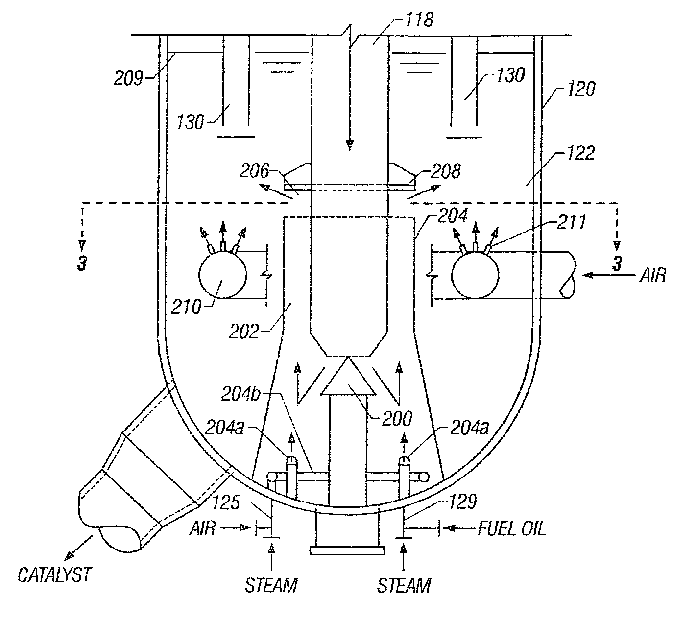
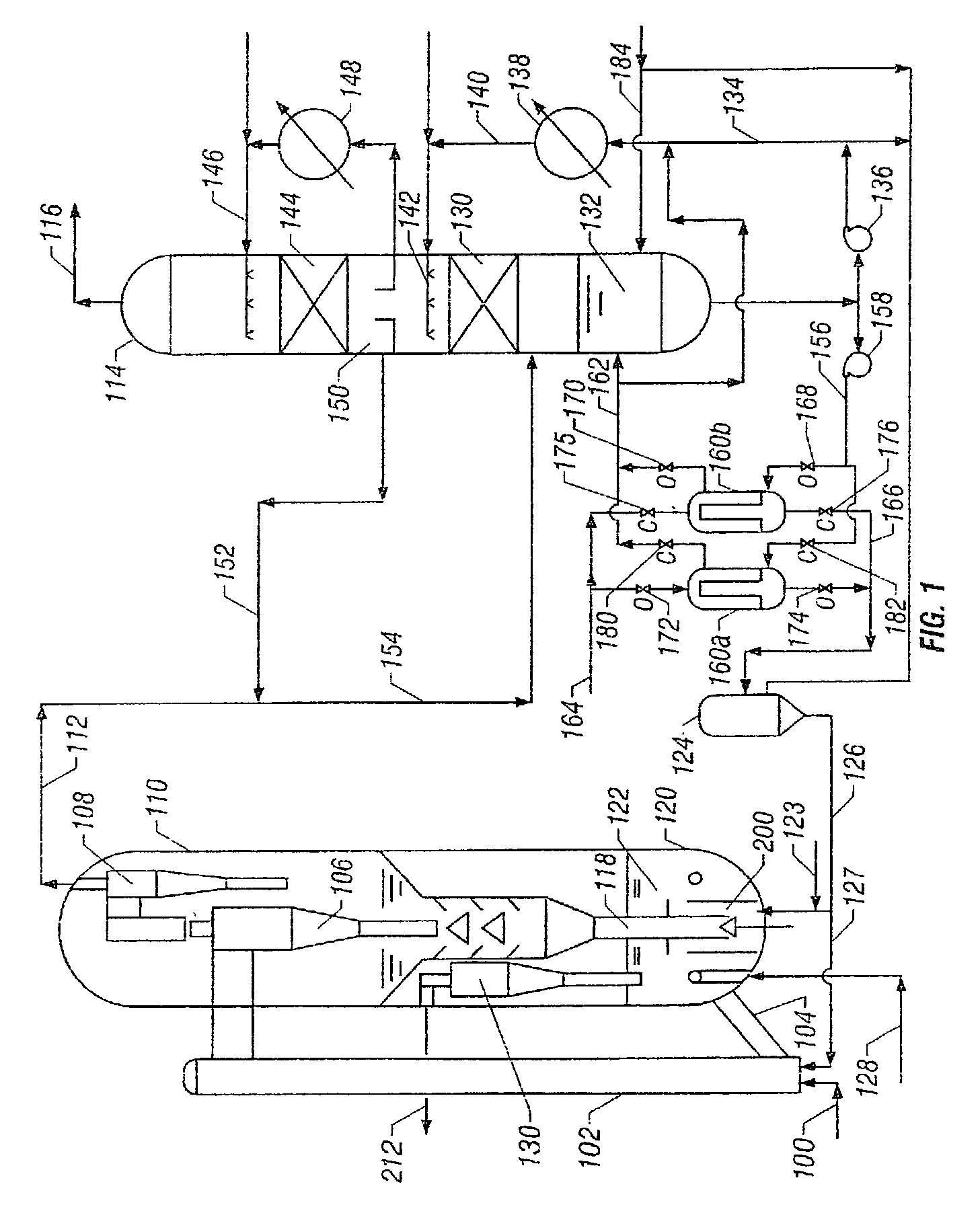
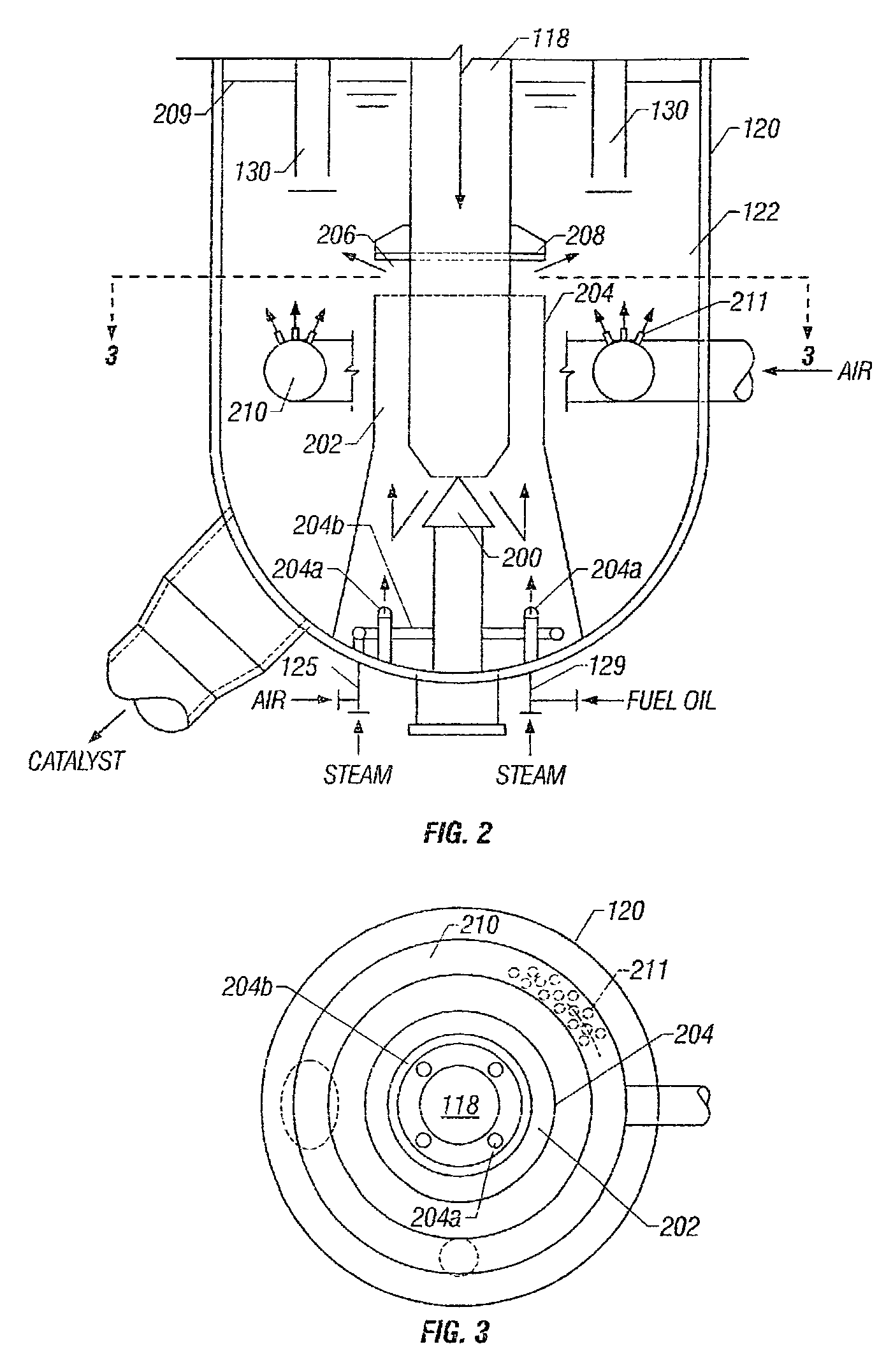
[0027]The present invention is a method and system for recovering fines from the light FCC effluent and regenerating spent catalyst. As used in the specification and claims, a light FCC unit or process is one in which the hydrocarbon feedstock to the FCC riser has a very low resid content such that there is insufficient carbon deposited on the catalyst to sustain combustion for regeneration without a supplemental fuel source, and there is insufficient fuel oil in the riser effluent for conventional slurry oil recovery, i.e. less than 2 weight percent of the hydrocarbons in the reactor effluent gases from the riser have an atmospheric boiling point above 550° F. (288° C.). However, if this amount is greater than 2 weight percent, the filters can optionally be bypassed and this material used as the slurry. The FCC process encompasses a fluidized catalytic reaction system, converting a light hydrocarbon feed stream preferably having a high olefin content to a product slate rich in prop...


PUM

PropertyMeasurementUnit
boiling pointaaaaaaaaaa
weight percentaaaaaaaaaa
temperatureaaaaaaaaaa

Abstract

A catalyst regenerator for regenerating spent light FCC catalyst and heating the catalyst to supply heat to an FCC reactor. The regenerator has discharge outlets for catalyst and off gas and a valve for introducing spent catalyst through a central stand pipe portion. The regenerator houses a dense phase catalyst bed. A centerwell receives a lower end of the standpipe portion and defines an annulus therebetween. The spent catalyst is introduced through the standpipe portion into the annulus. A fuel distributor introduces fuel into the centerwell for mixing with the catalyst in the annulus. A fluidization distributor introduces fluidization gas into the centerwell for fluidizing the catalyst in the annulus. A radial slot in the centerwell introduces the catalyst and fuel mixture from the annulus below the upper surface of the dense phase bed. An air distributor located below the radial slot introduces combustion air into the dense phase bed.

Description

BACKGROUND OF INVENTION[0001]The present invention relates to catalyst recovery from a light FCC-type effluent, and also to regeneration of the recovered catalyst.[0002]It has been proposed to produce light olefins such as ethylene and propylene from mixtures of heavier paraffin and olefins using a fluid catalytic cracking (FCC) system with the reaction conditions described, for example, in U.S. Pat. No. 5,043,522 to Leyshon et al.; U.S. Pat. No. 5,171,921 to Gaffney et al.; and U.S. Pat. No. 6,118,035 Fung et al. In this system, particulated catalyst and feedstock enter a reactor under specific reaction conditions. The reactor effluent is processed in a series of cyclone separators, usually housed in a vessel, that separate most of the catalyst from the effluent to be regenerated for recycle to a regenerator and then to the reactor, in a manner similar to conventional refinery FCC operations. The catalyst-lean hot effluent gases from the cyclones are then cooled and separated by fr...

Claims


Application Information

Patent Timeline
Patent Type & Authority Patents(United States)
IPC IPC(8): B01J8/18B01J8/24B01J8/26C10G11/18C10G9/32B01J38/00B01J8/00B01J38/02B01J38/12B01J38/30C07C4/06
CPCB01J8/003B01J8/1818B01J8/1827C10G11/182B01J2219/00024
Inventor PETERSON, ROBERT B.SANTNER, CHRISTALLMAN, MICHAEL
Owner KELLOGG BROWN & ROOT LLC
Why Eureka
Try Eureka