Ruggedized scintillation detector for portal monitors and light pipe incorporated therein

a scintillation detector and portal monitor technology, applied in radiation measurement, instruments, measurement devices, etc., can solve the problems of high background counts, high degree of shock or vibration exposure, and often subjected to varying degrees of radiation detectors of portal monitoring during normal use, so as to reduce the attenuation of low-energy gamma rays and reduce the attenuation

Inactive Publication Date: 2006-12-26
GENERAL ELECTRIC CO
View PDF12 Cites 11 Cited by
  • Summary
  • Abstract
  • Description
  • Claims
  • Application Information

AI Technical Summary

Benefits of technology

[0005]This invention provides a ruggedized portal monitoring radiation detector with a unique suspension / protection system. Generally, the detector will include a scintillation crystal (usually sodium iodide doped with thallium, but not excessively so); an axial suspension system for both the PMT as well as the scintillating crystal; a radial suspension system for the scintillating crystal to protect it from shock and vibration and to reduce gamma attenuation; an optically modeled light pipe to transmit the light generated by the crystal to the PMT; a square photomultiplier tube (PMT); and an aluminum housing enclosing the crystal to further reduce the attenuation of low energy gamma rays.
[0007]The detector in the exemplary embodiment incorporates a square PMT of the type typically utilized in medical imaging applications. These PMT's are also easy to obtain and are known to have excellent spectral resolution properties. The detector will utilize quartz as the material of choice for the light pipe; however, materials with similar indices of refraction may also be used if they offer additional benefits such as reduced cost, ease of manufacture, etc.
[0009]The detector's axial suspension system includes two annular wave springs located at one end of the crystal, remote from the PMT. Compression plates to evenly distribute the load of the springs and the crystal are located on either side of the springs. The axial suspension arrangement also includes an annular wave spring around the base of the PMT. These axial suspension springs are used to maintain optical coupling between the crystal, the light pipe and PMT. Foam pads or other similar materials may be used in conjunction with the other design components to achieve the same effect as the wave springs around either the PMT or at the ends of the crystal.
[0010]The detector housing includes a main or crystal housing enclosing the crystal component and a cylindrical cover that encloses the PMT and associated electronics package. The main housing portion may be composed of a thin-walled aluminum material that will reduce the degree of gamma radiation attenuation that occurs, thus enabling the detector to measure lower energy levels of gamma radiation. Additionally, with the incorporation of the suspension system as described above, the crystal is off-set from the housing wall, thus allowing for additional protection of the side of the detector in the event that the housing is impacted in some way. Finally, since the crystal is not in intimate contact with metal, an air gap or layer of insulating air is created between it and the housing. Thus, the crystal is also less likely to suffer from thermal shock.
[0013]In still another aspect, the invention relates to a radiation detector comprising a housing, an elongated, rectangular crystal having four longitudinally extending corners, and a photomultiplier tube both supported in the housing, with a light pipe located axially between respective facing ends of the photomultiplier tube and the crystal; a plurality of rails including shock absorbing material extending along the crystal, creating a gap between the crystal and the housing, for protecting the crystal from radial shock and vibration; and a plurality of resilient members opposite ends of the crystal for protecting the crystal from axial shock and vibration.

Problems solved by technology

Existing portal monitoring radiation detectors are often subjected to varying degrees of shock or vibration during normal usage.
In some cases, the degree of shock or vibration exposure may be quite severe.
Deleterious effects from shock and vibration may include high background counts, noise in the detector's response spectrum, and even breakage of the detector.
Due to size constraints in portal monitoring radiation detectors, these methods are commonly not even attempted.
The crystal and the PMT are commonly glued to the light pipe interface, but frequently become uncoupled, however, due to shock, vibration, temperature fluctuations, or other typical field exposures.
Moreover, the stainless steel housing and any internal isolation systems that may be employed typically reduce the detector's effectiveness to measure gamma radiation at low energy levels due to their attenuating effects.
Finally, the light pipes and photomultiplier tubes (PMTs) used in these types of detectors are not optimized for light transmission and collection.

Method used


Image

  • Ruggedized scintillation detector for portal monitors and light pipe incorporated therein
  • Ruggedized scintillation detector for portal monitors and light pipe incorporated therein
  • Ruggedized scintillation detector for portal monitors and light pipe incorporated therein

Examples


Embodiment Construction

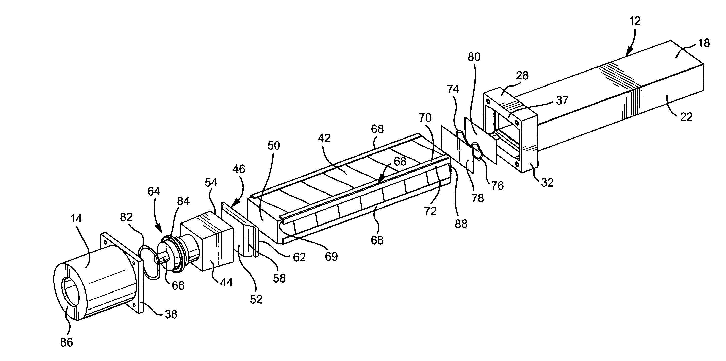
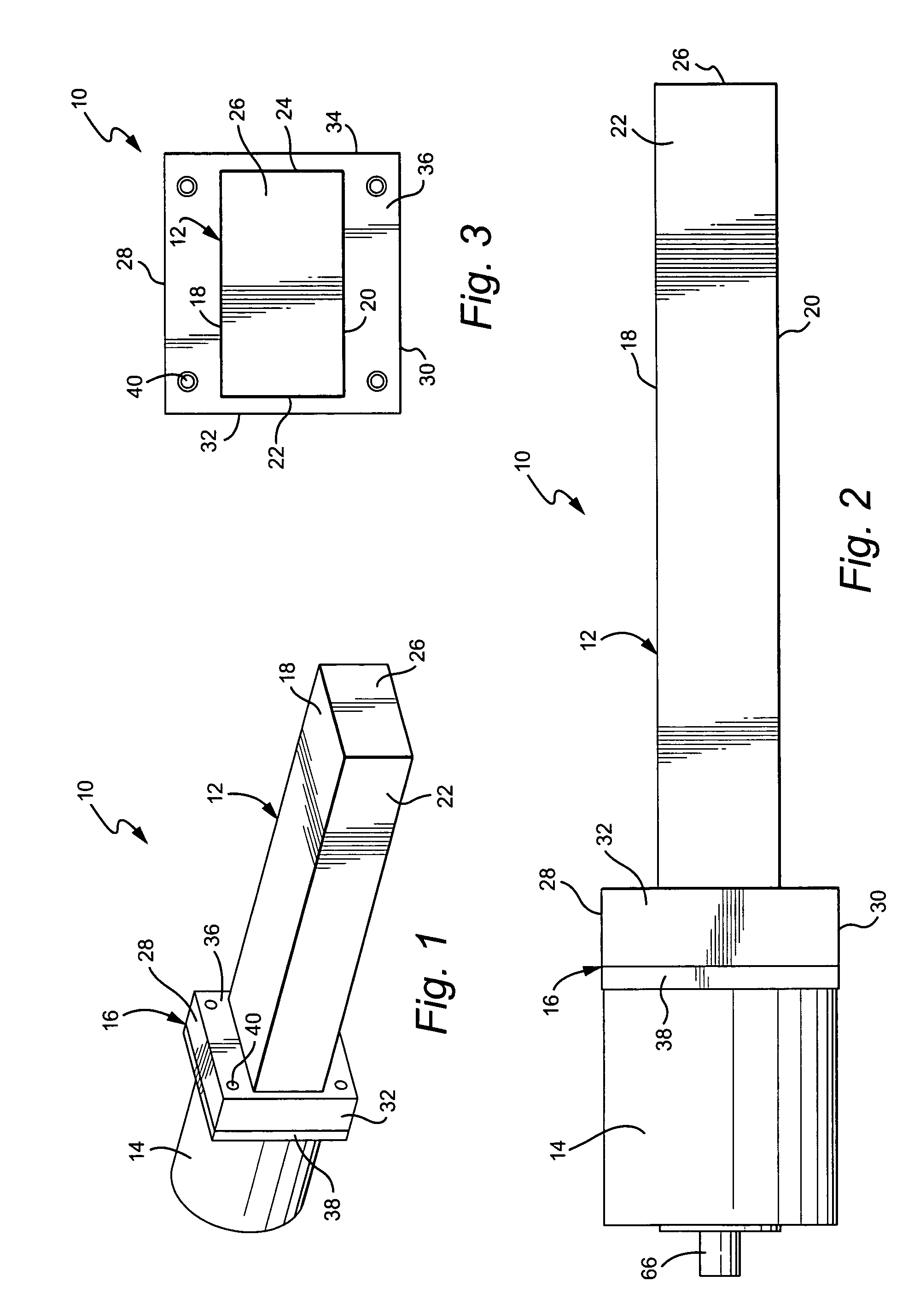
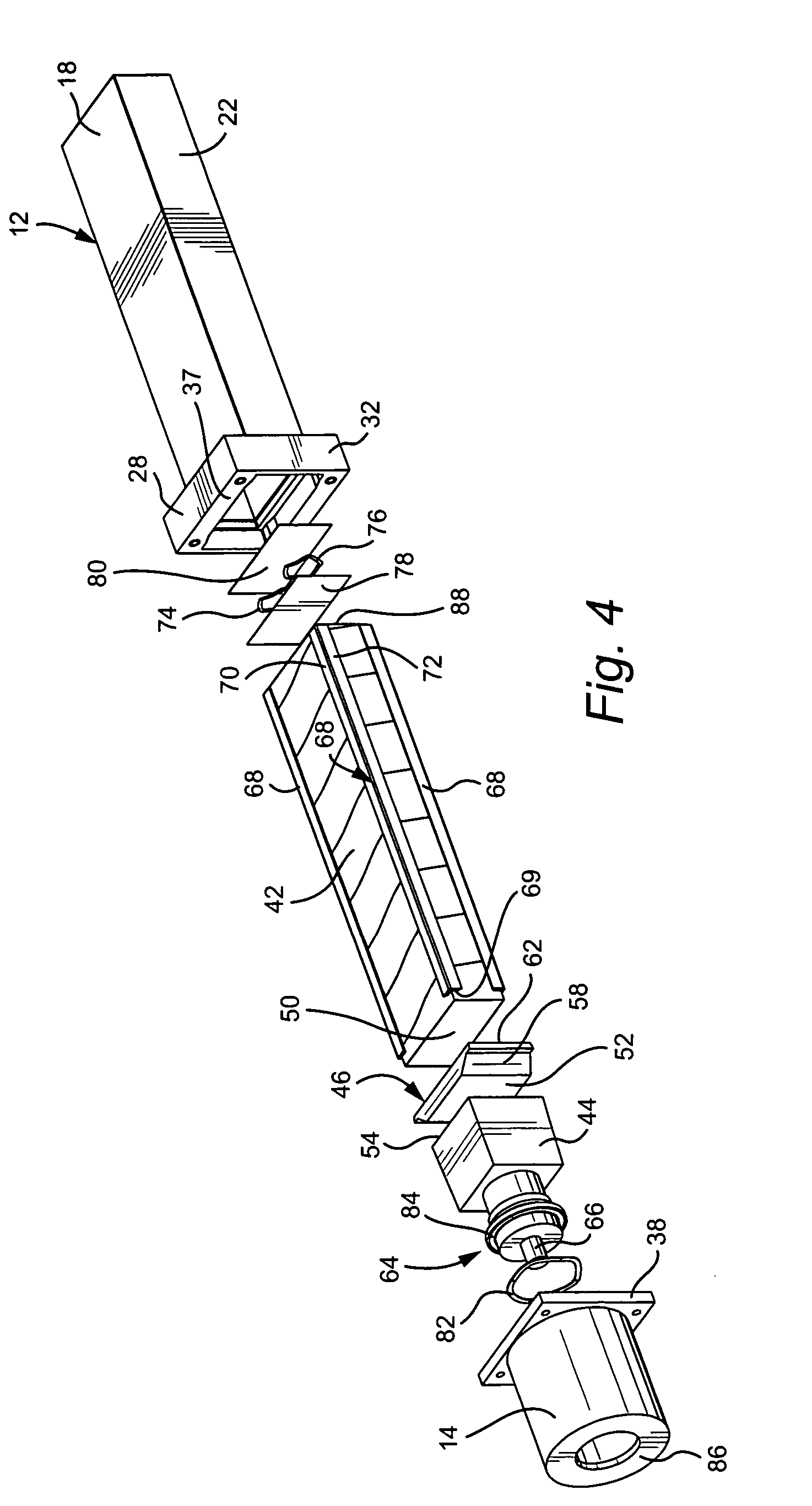
[0023]With initial reference to FIGS. 1–3, a portal monitoring radiation detector 10 includes a housing including a main or crystal housing 12 and a PMT cover 14 joined together at a housing interface 16. The main housing portion 12 is of generally elongated rectangular shape, having top and bottom walls 18, 20, side walls 22, 24 and an end wall 26. The opposite end of the crystal housing is enlarged, particularly in terms of the height dimension of the housing, and includes top and bottom walls 28, 30, side walls 32, 34 and an apertured end wall 36 joined to the remainder of the main housing 12. The opposite end wall 37 (also apertured) is sized to mate with a similarly shaped flange 38 on one end of the otherwise cylindrical PMT cover 14, facilitating the joining of the crystal housing 12 and PMT cover 14 by means of screw fasteners 40 or other suitable means. The crystal housing 12 may be constructed of thin-walled aluminum that will reduce the degree of gamma radiation detection...


PUM


Abstract

A radiation detector includes a housing, an elongated, rectangular crystal having four longitudinally extending corners, and a photomultiplier tube both supported in the housing, with a light pipe located axially between respective facing ends of the photomultiplier tube and the crystal; and a plurality of elongated rails extending along respective ones of the longitudinally extending corners of the rectangular crystal, establishing an air gap between the crystal and the housing.

Description

BACKGROUND OF THE INVENTION[0001]This invention relates generally to radiation detectors and, more specifically, to a suspension and protection system for portal monitoring radiation detectors.[0002]Existing portal monitoring radiation detectors are often subjected to varying degrees of shock or vibration during normal usage. In some cases, the degree of shock or vibration exposure may be quite severe. Deleterious effects from shock and vibration may include high background counts, noise in the detector's response spectrum, and even breakage of the detector.[0003]Existing shock and vibration isolation systems for radiation detectors typically consist of either an elastomeric boot that is telescoped over the radiation detector, or a foam pad that is wrapped around the radiation detector. Due to size constraints in portal monitoring radiation detectors, these methods are commonly not even attempted. In many cases, the crystal component of the detector is simply wrapped in a reflective...

Claims


Application Information

Patent Timeline
Patent Type & Authority Patents(United States)
IPC IPC(8): G01T1/20G01T1/202
CPCG01T1/202
Inventor CLARKE, LUCAS LEMARPALMER, BRIAN MARSHALLJOHANNING, JEFFREY LOUISJONES, KEITH DAVIDWILLIAMS, JAMES R.SHALHOUB, ANDREW EMANUEL
Owner GENERAL ELECTRIC CO
Why Eureka
Try Eureka