Method for controlling static magnetic field and MRI apparatus

a static magnetic field and control method technology, applied in the direction of instruments, magnetic bodies, using reradiation, etc., can solve the problem that the effect of preventing leakage flux cannot be sufficiently obtained, and achieve the effect of preventing leakage flux

Inactive Publication Date: 2006-12-26
GE MEDICAL SYST GLOBAL TECH CO LLC
View PDF20 Cites 9 Cited by
  • Summary
  • Abstract
  • Description
  • Claims
  • Application Information

AI Technical Summary

Benefits of technology

[0007]Therefore, an object of the present invention is to provide a static magnetic field control method and an MRI apparatus both capable of sufficiently obtaining the effect of shaping static magnetic fields and the effect of preventing leakage flux even when magnetic plates are taken off.
[0008]According to a first aspect, the present invention provides a static magnetic field control method comprising the steps of disposing a plurality of auxiliary magnets set to directions repellent to main magnets around the main magnets of a static magnetic field generating magnet, adjusting intervals among the main magnets and auxiliary magnets respectively to thereby shape static magnetic fields, and suppressing magnetic fields that leak to the peripheries of the main magnets.
[0009]In the static magnetic field control method according to the first aspect, the plurality of auxiliary magnets are disposed around the main magnets of the static magnetic field generating magnet so as to take the directions repellent to the main magnets. Then, the intervals among the main magnets and the auxiliary magnets are adjusted in such a manner that the static magnetic fields are shaped and expanded to the peripheries of the main magnets, and the leakage flux is canceled out. Consequently, the effect of shaping the static magnetic fields and the effect of preventing the leakage flux can be sufficiently obtained.
[0011]In the static magnetic field control method according to the second aspect, the spacers are respectively interposed among the main magnets and the auxiliary magnets to make it easy to fix the positions of the auxiliary magnets after the adjustment of the intervals.
[0027]The MRI apparatus according to the tenth aspect is capable of shaping static magnetic fields inside the main magnet according to a field direction of the main magnet and a field direction of each auxiliary magnet and suitably suppressing the leakage of magnetic fields around the main magnet.
[0029]In the MRI apparatus according to the eleventh aspect, the magnetization directions of the auxiliary magnets are tilted to thereby make it possible to shape static magnetic fields inside the main magnets and suitably suppress the leakage of magnetic fields around the main magnets.

Problems solved by technology

However, a problem arises in that when the magnetic plates are taken off for simplification of a configuration of the magnetic field generator, the effect of shaping the static magnetic fields and the effect of preventing the leakage flux cannot be sufficiently obtained in the case of the auxiliary magnets alone.

Method used


Image

  • Method for controlling static magnetic field and MRI apparatus
  • Method for controlling static magnetic field and MRI apparatus
  • Method for controlling static magnetic field and MRI apparatus

Examples


embodiment 1

[0053][Embodiment 1]

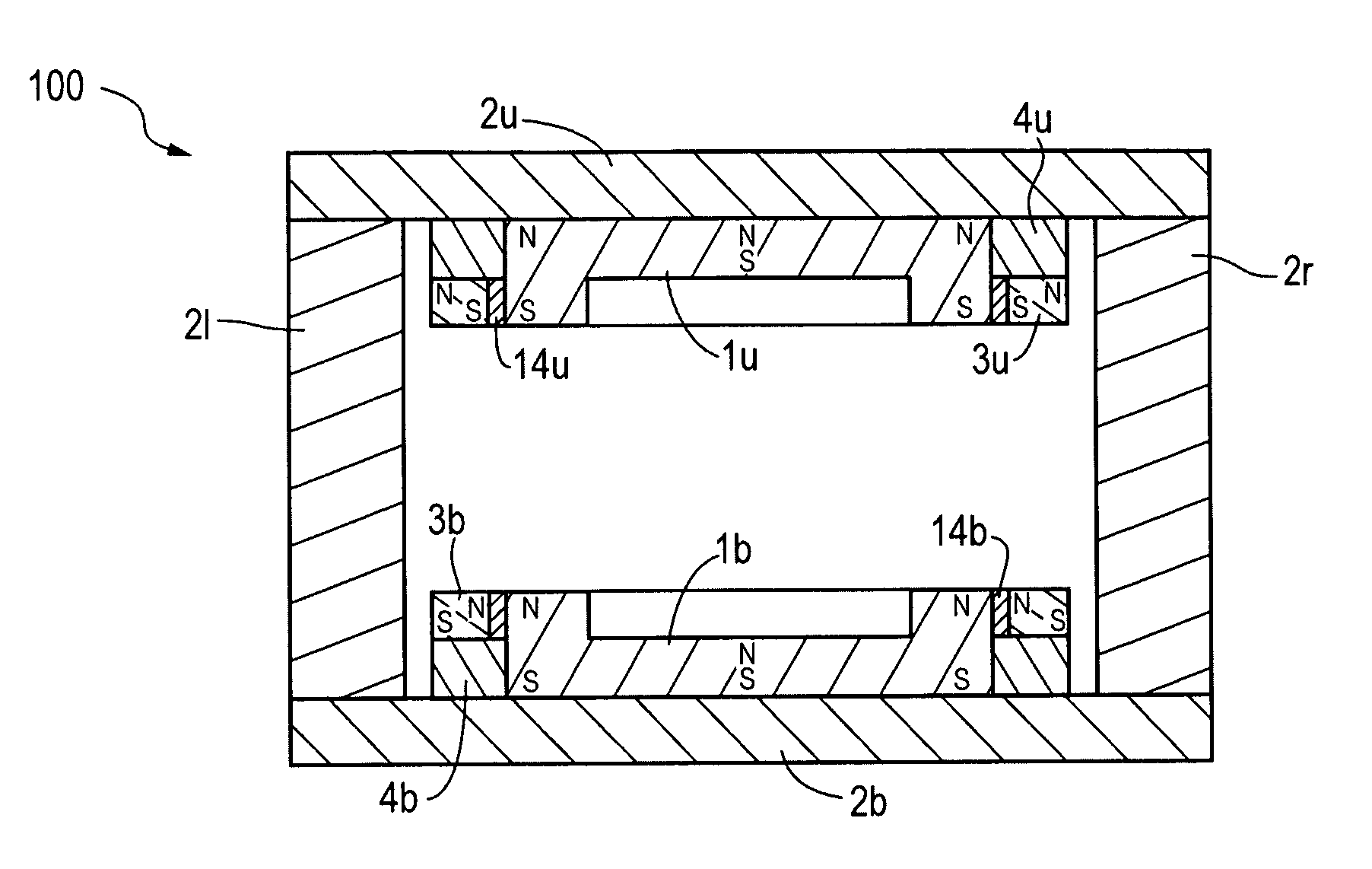
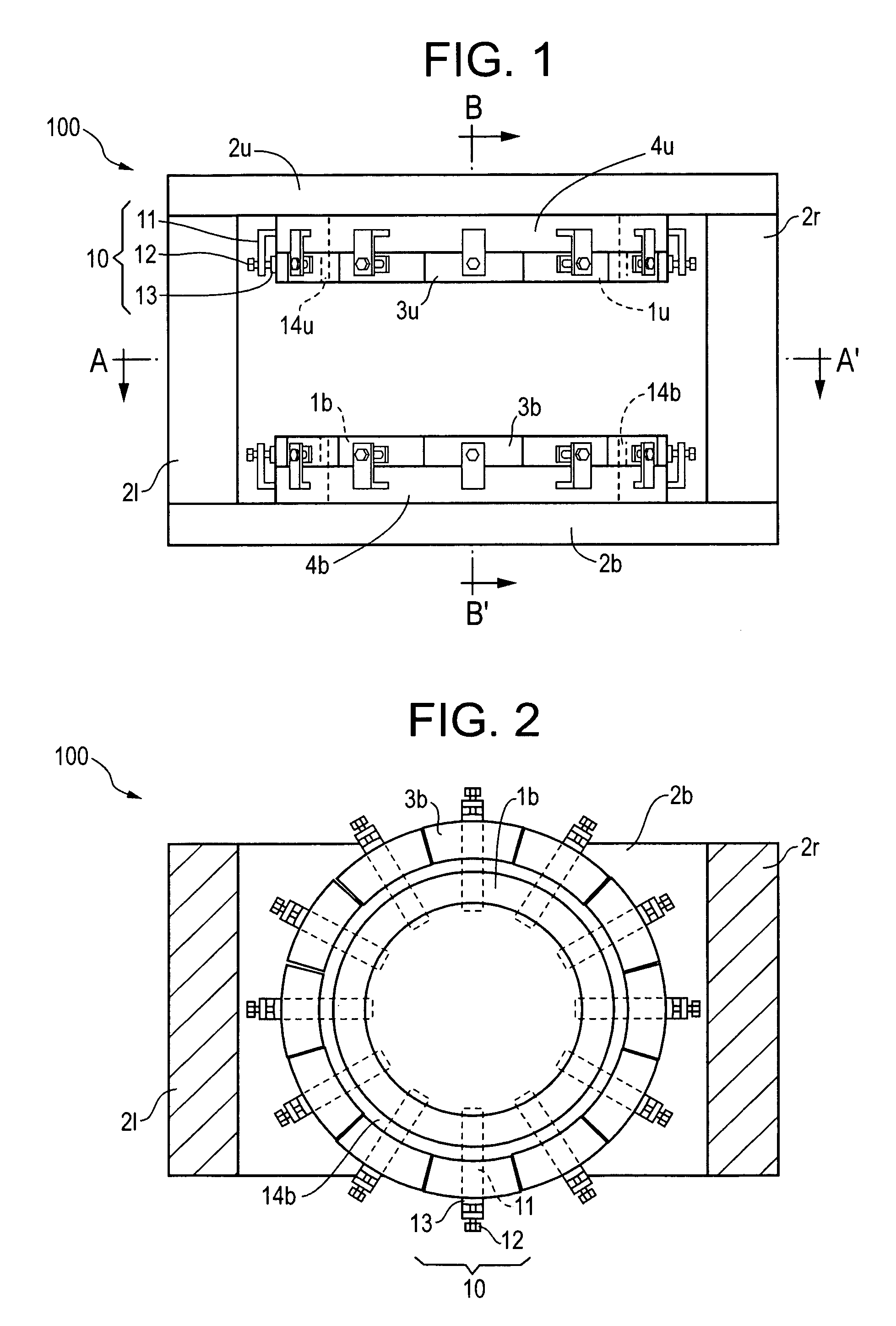
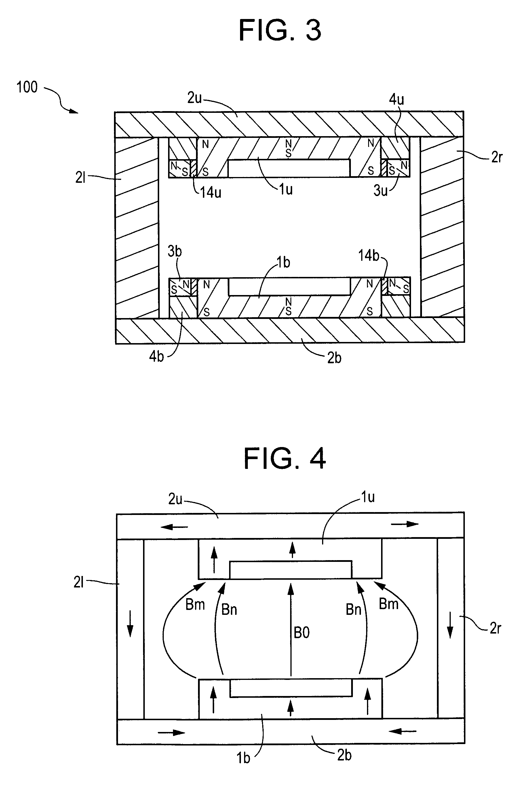
[0054]FIG. 1 is a front view showing a static magnetic field generating magnet section of an MRI apparatus 100 according to an embodiment 1. FIG. 2 is a cross-sectional view taken along line A–A′ of FIG. 1. FIG. 3 is a sectional typical view taken along line B–B′ of FIG. 1.

[0055]The MRI apparatus 100 is equipped with an upper main magnet 1u and a lower main magnet 1b of which the front surfaces are opposite to each other in the vertical direction with a space with an object placed therein being interposed therebetween, an upper yoke 2u, a right yoke 2r, a lower yoke 2b and a left yoke 2l which magnetically connect the back surfaces of the main magnets 1u and 1b, a plurality of upper auxiliary magnets 3u disposed around the upper main magnet 1u, an upper support table 4u for fixing the height of each upper auxiliary magnet 3u with respect to the upper yoke 2u, a plurality of lower auxiliary magnets 3b disposed around the lower main magnet 1b, a lower support table...

embodiment 2

[0072][Embodiment 2]

[0073]Spacers 14u and 14b may be formed of an adhesive mixed with a filler (e.g., ferrite bead) corresponding to a magnetic body.

[0074]Varying the material for the magnetic body and the amount of mixing thereof makes it possible to control the effects of auxiliary magnets 3u and 3b.

embodiment 3

[0075][Embodiment 3]

[0076]FIGS. 7 and 8 respectively show an MRI apparatus 200 according to an embodiment 3.

[0077]The MRI apparatus 200 has a gap g defined between an upper main magnet 1u and upper auxiliary magnets 3u and a gap g defined between a lower main magnet 1b and lower auxiliary magnets 3b.


PUM


Abstract

A Magnetic Resonance Imaging system includes a plurality of auxiliary magnets that are disposed around the main magnets to adjust the interval between the main magnet and the auxiliary magnets and the interval between the main magnet and the auxiliary magnets respectively.

Description

CROSS REFERENCE TO RELATED APPLICATIONS[0001]This application claims the benefit of Japanese Application No. 2004-153333 filed May 24, 2004.BACKGROUND OF THE INVENTION[0002]The present invention relates to a static magnetic field control method and an MRI (Magnetic Resonance Imaging) apparatus, and more specifically to a static magnetic field control method and an MRI apparatus both capable of sufficiently obtaining the effect of shaping static magnetic fields and the effect of preventing a magnetic leakage flux.[0003]There has heretofore been known a magnetic field generator wherein leakage flux preventing auxiliary magnets are provided outside magnetic plates placed on opposite surfaces of main magnets of a static magnetic field generating magnet (see patent document 1).[0004][Patent Document 1] Japanese Unexamined Patent Publication No. 2003-168604.[0005]In the conventional magnetic field generator, magnetic plates are provided on opposite surfaces of main magnets, static magneti...

Claims


Application Information

Patent Timeline
Patent Type & Authority Patents(United States)
IPC IPC(8): G01V3/00A61B5/055G01R33/383G01R33/3873
CPCG01R33/383G01R33/3873A61B5/05A61B5/055
Inventor GOTO, TAKAOSATO, TAKAMI
Owner GE MEDICAL SYST GLOBAL TECH CO LLC
Why Eureka
Try Eureka