
Method and system for measuring crosstalk utilizing a crossbar switch

Inactive Publication Date: 2006-12-26
CISCO TECH INC
View PDF11 Cites 25 Cited by
  • Summary
  • Abstract
  • Description
  • Claims
  • Application Information

AI Technical Summary

Benefits of technology

[0004]The present invention provides a system for measuring crosstalk utilizing a crossbar switch that substantially eliminates or reduces at least some of the disadvantages and problems associated with previous systems for measuring crosstalk.
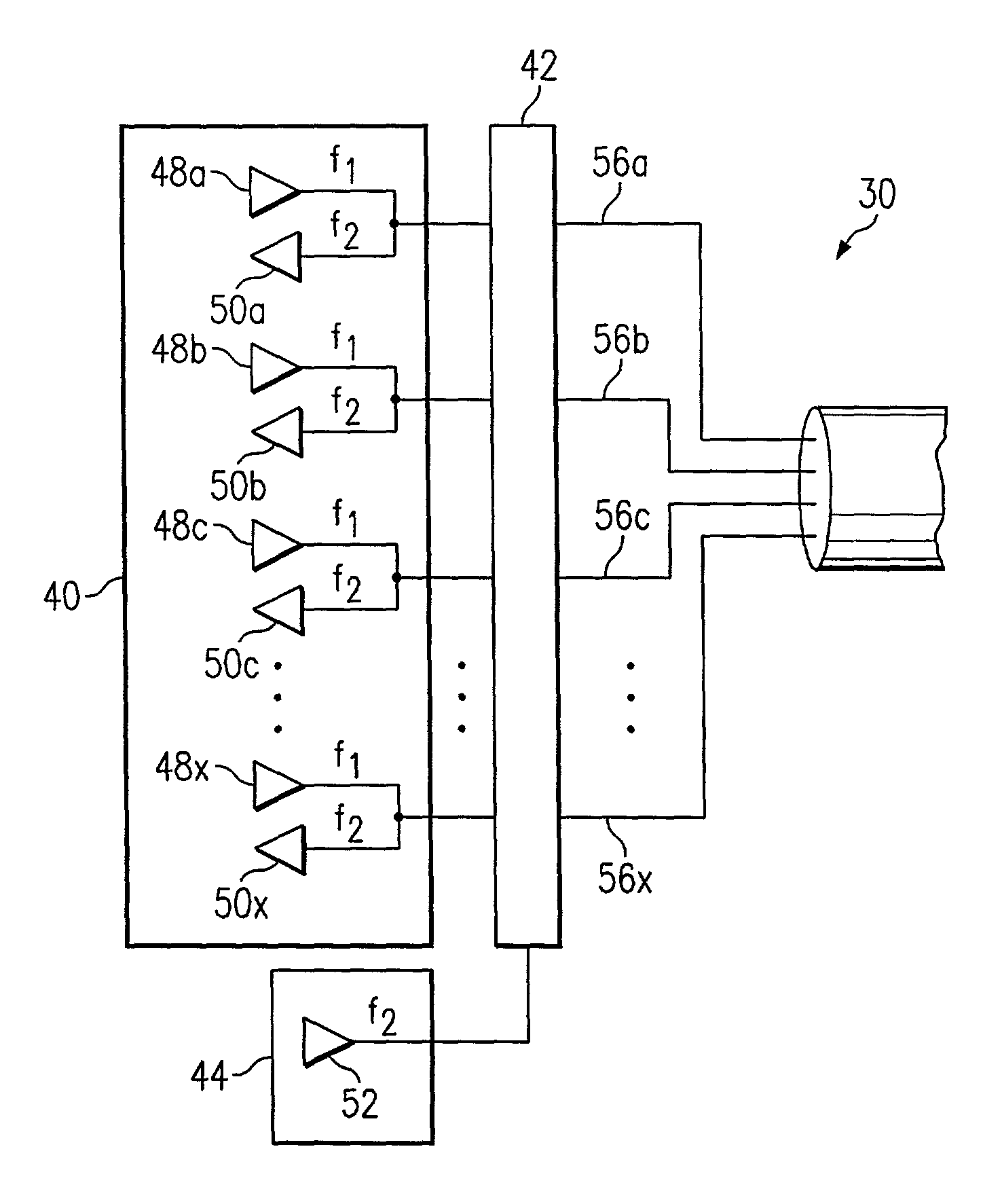
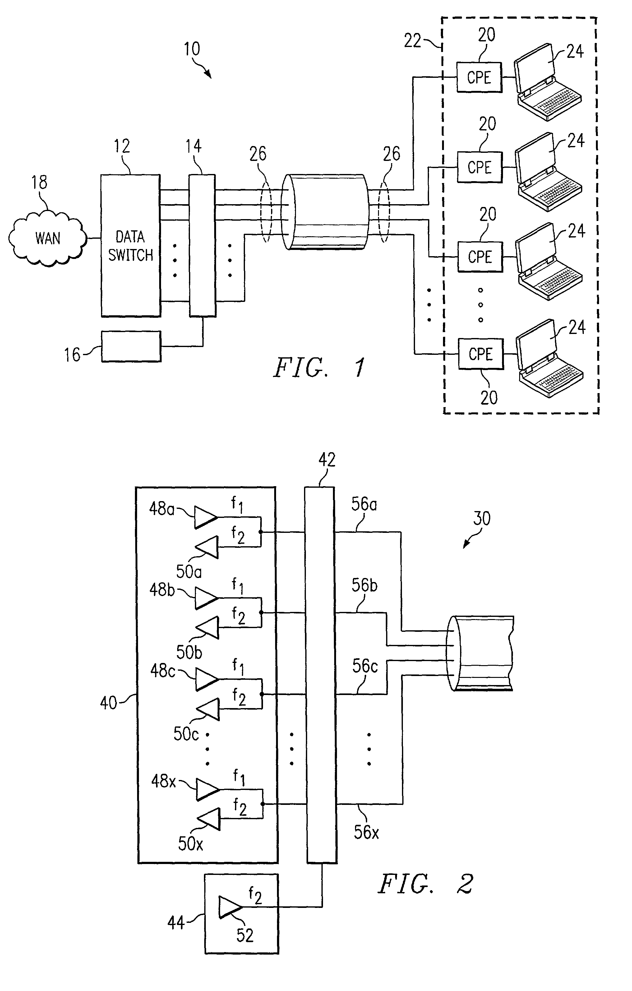
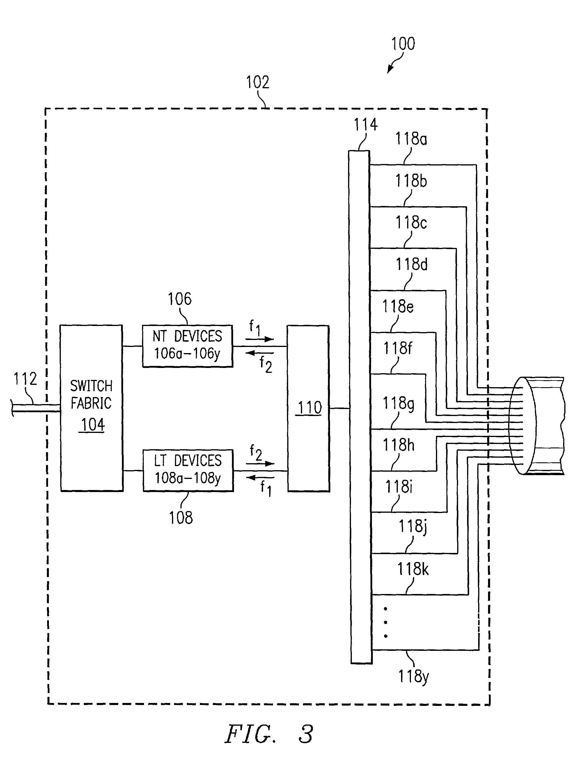
[0007]Technical advantages of particular embodiments of the present invention include a crosstalk measurement system with a solid state crossbar switch that couples transmitters and receivers to data lines of a data service system. The measurement system can measure crosstalk on each data line without having to manually or mechanically couple the transmitters and receivers to the data lines. Accordingly, crosstalk can be quickly measured in the data service system.
[0009]Yet another technical advantage of particular embodiments of the present invention includes a crosstalk measurement system through which an accurate estimation of FEXT may be obtained. Such estimation may be obtained by installing a CPE device at an endpoint of one or more data line without requiring the installation of a CPE device at an endpoint of each data line.

Problems solved by technology

Communication occurring on one wire may degrade or substantially interrupt communication on an adjacent wire by causing crosstalk on the adjacent wire.
DSL systems typically can suffer from two different types of crosstalk.
Far end crosstalk typically may not be avoided and may only limit the speed of communication in the system.
Near end crosstalk, however, has a more detrimental effect on communication in the system and may even destroy weak line communication if it is not eliminated.

Method used


Image

  • Method and system for measuring crosstalk utilizing a crossbar switch
  • Method and system for measuring crosstalk utilizing a crossbar switch
  • Method and system for measuring crosstalk utilizing a crossbar switch

Examples


Embodiment Construction

[0015]FIG. 1 illustrates a system 10 for measuring crosstalk in a system providing data services, in accordance with an embodiment of the present invention. System 10 is a data service system that may provide data services, such as long reach Ethernet (LRE) service, for a subscriber community 22, which may include one or more businesses, apartment complexes or other communities in which one or more subscribers share communications infrastructure or resources, such as a crossbar switch 14. Each subscriber in subscriber community 22 may access data services using one or more associated personal computers (PCs) 24, as illustrated, or other suitable devices, such as telephones or televisions, for interfacing with a data network, such as wide area network (WAN) 18.

[0016]System 10 includes a solid state crossbar switch 14 which couples a data switch 12 with customer premise equipment (CPE) devices 20. Data lines 26 couple crossbar switch 14 to CPE devices 20. Data switch 12 is linked to W...


PUM


Abstract

A method for measuring crosstalk in a data service system includes transmitting a signal using a first device. The first device is coupled to a solid state crossbar switch. The method includes coupling the first device using the crossbar switch to a first data line coupled to the crossbar switch such that the signal communicates over the first data line. The first data line is capable of being coupled to a customer premise equipment (CPE) device. The method includes coupling a first number of second devices coupled to the crossbar switch to a second number of data lines coupled to the crossbar switch using the crossbar switch. Each second number of data lines is capable of being coupled to a CPE device. The method also includes monitoring the second number of data lines for near end crosstalk (NEXT) generated by the signal communicating over the first data line using the first number of second devices. The method may also include monitoring at least one of a third number of data lines for far end crosstalk (FEXT) generated by a signal communicating over the third number of data lines. The third number of data lines comprises the first data line and the second number of data lines.

Description

TECHNICAL FIELD OF THE INVENTION[0001]This invention relates in general to the field of data communications and, more particularly, to a system for measuring crosstalk utilizing a crossbar switch.BACKGROUND OF THE INVENTION[0002]The recent growth of the Internet has increased the demand for bandwidth. Digital subscriber line (DSL) technology meets this demand by providing higher bandwidth data service over existing twisted pair telephone lines. DSL technology achieves the higher data transmission rates by taking advantage of unused frequencies, which are significantly higher than voice band frequencies, on the existing twisted pair lines.[0003]DSL systems typically include multiple bundles of twisted pair wires that may be located within close proximity of each other. Communication occurring on one wire may degrade or substantially interrupt communication on an adjacent wire by causing crosstalk on the adjacent wire. DSL systems typically can suffer from two different types of cross...

Claims


Application Information

Patent Timeline
IPC IPC(8): H04J1/12
CPCH04B3/487
Inventor BARRASS, HUGHSIMON, SCOTT M.
Owner CISCO TECH INC
Learn More