Projection gating of x-ray CT scan

a ct scan and projection gating technology, applied in the field of ct imaging methods and apparatuses, can solve the problems of difficult to produce an image without artifacts, inducing image artifacts, and assumption not always correct, and achieve the effect of improving x-ray ct images

Inactive Publication Date: 2006-12-26
RGT UNIV OF MICHIGAN
View PDF12 Cites 17 Cited by
  • Summary
  • Abstract
  • Description
  • Claims
  • Application Information

AI Technical Summary

Problems solved by technology

When an image is acquired of the beating heart or surrounding tissues, it is difficult to produce an image without artifacts.
Motion induced image artifacts result from such heart motion.
This assumption is not always correct.
This creates real problems for ECG gating in that the fractions of the QRS interval that might successfully produce consistent data for static / gated images before injection would not be the same after contrast injection.

Method used


Image

  • Projection gating of x-ray CT scan
  • Projection gating of x-ray CT scan
  • Projection gating of x-ray CT scan

Examples


Embodiment Construction

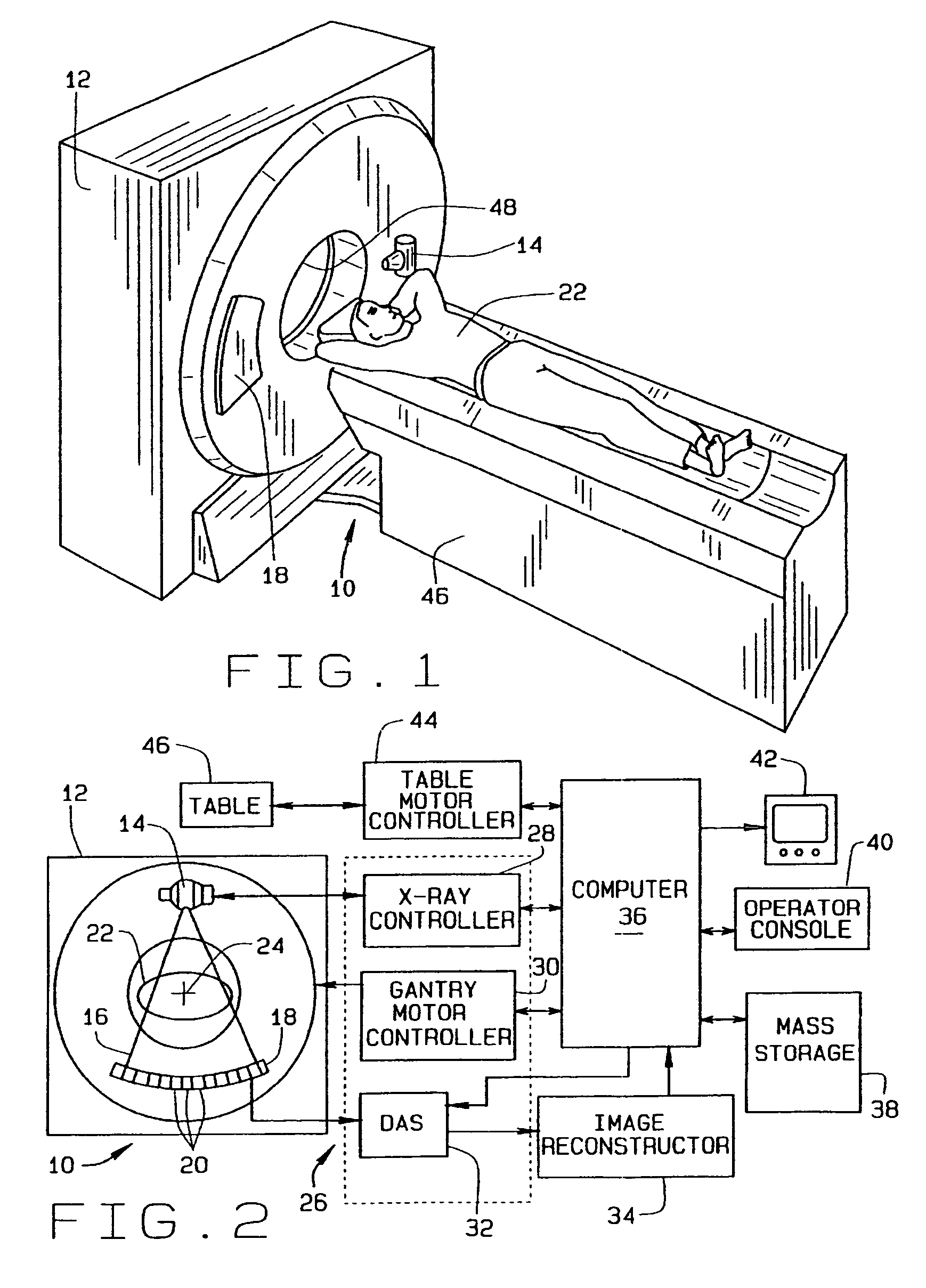
[0023]Referring to FIGS. 1 and 2, a computed tomography (CT) imaging system 10 is shown as including a gantry 12 representative of a “third generation” CT scanner. Gantry 12 has an x-ray source 14 that projects a beam of x-rays 16 toward a detector array 18 on the opposite side of gantry 12. Detector array 18 is formed by detector elements 20 which together sense the projected x-rays that pass through an object, such as a medical patient 22. Each detector element 20 produces an electrical signal that represents the intensity of an impinging x-ray beam and hence the attenuation of the beam as it passes through object or patient 22. During a scan to acquire x-ray projection data, gantry 12 and the components mounted thereon rotate about a center of rotation 24. In one embodiment, and as shown in FIG. 2, detector elements 20 are arranged in one row so that projection data corresponding to a single image slice is acquired during a scan. In another embodiment, detector elements 20 are ar...


PUM

PropertyMeasurementUnit
timeaaaaaaaaaa
medical imagingaaaaaaaaaa
CTaaaaaaaaaa

Abstract

An x-ray CT system performs a scan by acquiring projection views from which an image is reconstructed. In a prospective embodiment, the correlation of adjacent views is calculated as the scan is performed and is used to detect subject motion as the scan is being performed. In a retrospective embodiment, the correlation of adjacent views is calculated and is used to detect subject motion after the scan is completed. In the first embodiment substitute projection views are acquired by continuing the scan and in the second embodiment redundant projection views acquired during the scan are substituted until the best possible image is produced.

Description

CROSS-REFERENCE TO RELATED APPLICATIONS[0001]This application claims the benefit of U.S. Provisional patent application Ser. No. 60 / 608,333 filed on Sep. 9, 2004 and entitled “Projection Gating Of X-Ray Scan”.BACKGROUND OF THE INVENTION[0002]This invention relates generally to methods and apparatus for CT imaging and other radiation imaging systems and, more particularly, to a method for reducing image artifacts caused by subject motion.[0003]In at least some “computed tomography” (CT) imaging system configurations, an x-ray source projects a fan-shaped beam which is collimated to lie within an X-Y plane of a Cartesian coordinate system, generally referred to as an “imaging plane”. The x-ray beam passes through a subject being imaged, such as a patient. The beam, after being attenuated by the object, impinges upon an array of radiation detectors. The intensity of the attenuated radiation beam received at a detector array is dependent upon the attenuation of the x-ray beam by the obj...

Claims


Application Information

Patent Timeline
Patent Type & Authority Patents(United States)
IPC IPC(8): G01N23/083
CPCA61B6/032A61B6/5217A61B6/5264A61B6/541G06T11/005A61B6/503G06T2211/412A61B6/027G16H50/30
Inventor RUBIN, JONATHAN M.DESJARDINS, BENOITFOWLKES, J. BRIANTRIDANDAPANI, SRINI
Owner RGT UNIV OF MICHIGAN
Why Eureka
Try Eureka