Testing apparatus for compression and shear testing of a test component such as a curved aircraft component

Inactive Publication Date: 2007-01-02
AIRBUS OPERATIONS GMBH
View PDF9 Cites 15 Cited by
  • Summary
  • Abstract
  • Description
  • Claims
  • Application Information

AI Technical Summary

Benefits of technology

[0029]A substantial advantage of the inventive arrangement is that the elements for introducing the shear forces act to compensate a length change or variation (especially an uneven length change), arising due to the compression loading, of the aircraft component being tested. In this regard, in an advantageous manner, the shear load is introduced into the vertical edges of the aircraft component according to prescribed requirements at a specified pattern spacing or raster of preferably 100 mm. The general arrangement of the hydraulic cylinders integrated into the respective shear beams may be advantageously maintained, although this is not absolutely necessary in the inventive apparatus. The integrated hydraulic cylinders of the shear beams are modified according to the invention so that the required shear load of, for example, 1700 N / mm can be transmitted through these cylinders. This requires a hydraulic pressure of about 900 bar. In this pressure range, a direct servo-hydraulic proportional regulation is not possible. An advantage of the invention is that the inventive modified shear beam arrangement now serves as a passive force introduction element with a length compensation or balancing function.
[0030]Throughout this specification, the term “hydraulic cylinder” refers to a hydraulic piston-cylinder device having any suitable structure.

Problems solved by technology

It is a disadvantage of the previously known conventional apparatuses that they can only be used for a hydraulic pressure up to about 350 bar, because a direct regulation is no longer possible for higher pressures in the hydraulic system.

Method used


Image

  • Testing apparatus for compression and shear testing of a test component such as a curved aircraft component
  • Testing apparatus for compression and shear testing of a test component such as a curved aircraft component

Examples


Embodiment Construction

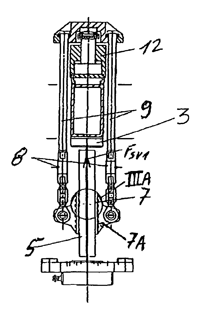
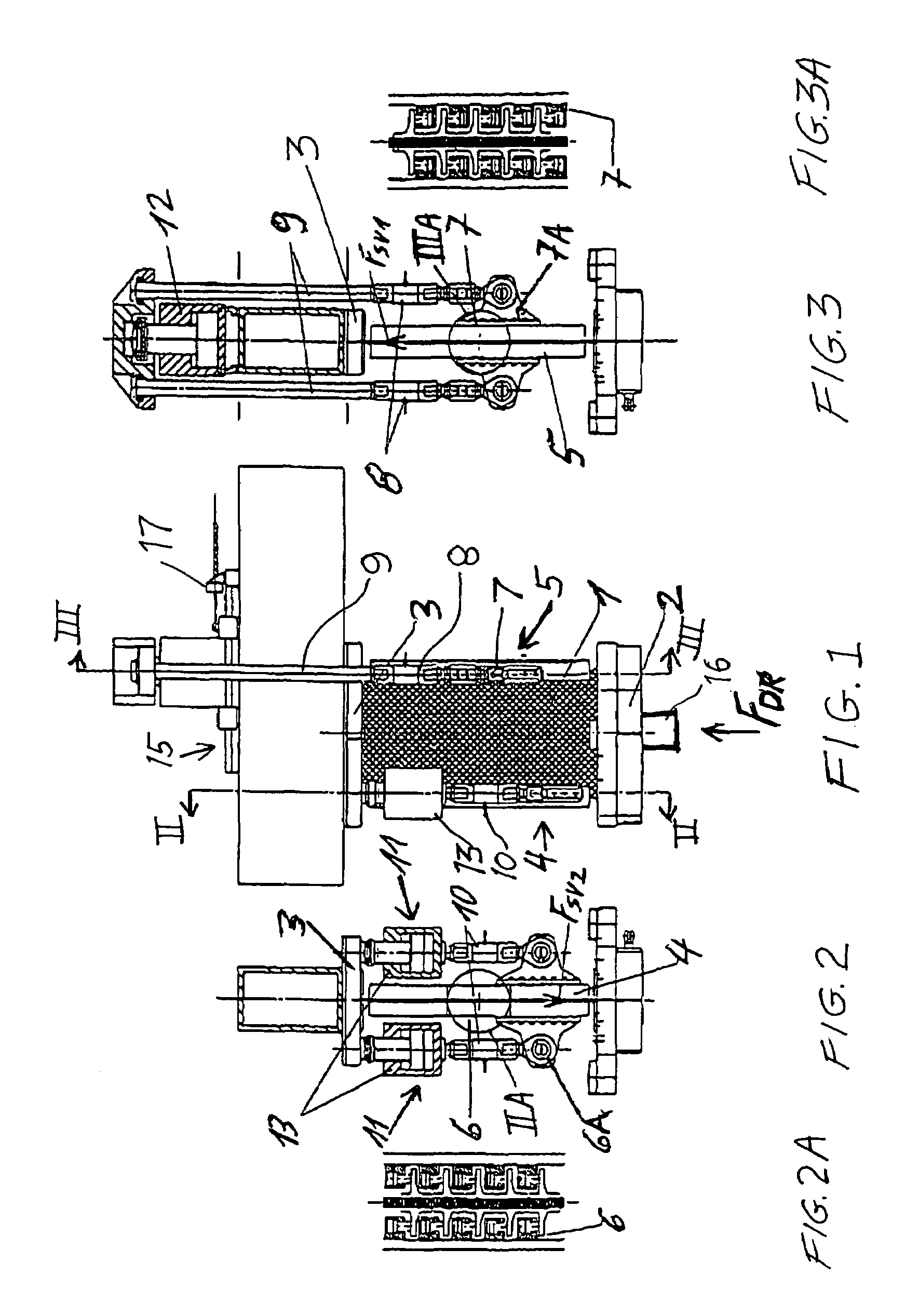
[0037]The inventive testing apparatus for compression and shear testing of a test component such as a curved aircraft component 1 (e.g. an aircraft fuselage shell component), includes an arrangement for applying a vertically directed compression force FDR (see FIG. 1), an arrangement for applying an upwardly directed shear force FSV1 to one vertical edge of the component 1 (see FIG. 3), and another arrangement for applying a downwardly directed vertical shear force FSV2 to the opposite vertical edge of the component 1 (see FIG. 2). The inventive apparatus shares many features and a basic construction with the conventional apparatus that has been described above in the Background Information section, and modifies and adds certain new inventive features and components relative to the conventional apparatus.

[0038]The main compression load FDR is introduced vertically into the test component such as an aircraft component 1 through a force introduction table 2, which is moved by a force-...


PUM

PropertyMeasurementUnit
pressuresaaaaaaaaaa
hydraulic pressureaaaaaaaaaa
forceaaaaaaaaaa

Abstract

A testing apparatus receives a test component between a force introduction table and a pressure plate, which apply a compressive load to the component therebetween. First and second shear beams are secured to opposite vertical edges of the component to respectively introduce upwardly and downwardly directed shear forces into the component. The upwardly directed shear force is generated by a first hydraulic cylinder that is arranged above the pressure plate in a horizontally adjustable manner on a head frame, and that is connected to the first shear beam through two tension rod assemblies including tensile force measuring transducers. The downwardly directed shear force is generated by two second hydraulic cylinders that are arranged under the pressure plate and that are connected to the second shear beam by strut assemblies including compressive force measuring transducers. High shear loads can be applied in the same vertical plane as the compressive load.

Description

PRIORITY CLAIM[0001]This application is based on and claims the priority under 35 U.S.C. §119 of German Patent Application 103 44 855.0, filed on Sep. 26, 2003, the entire disclosure of which is incorporated herein by reference.FIELD OF THE INVENTION[0002]The present invention relates to an apparatus for introducing compression and shear forces into a test component or test specimen such as a curved aircraft component, for carrying out the compression and shear load testing of the component.BACKGROUND INFORMATION[0003]Various load testing apparatuses are known, including apparatuses for carrying out simultaneous compressive loading and shear loading of a test component that is to be load tested.[0004]Generally, in such known apparatuses, the compression load may be introduced into the test component by means of a force introduction table and a pressure plate acting as a counter-support, between which the test component is received. For example, a force-regulated hydraulic cylinder a...

Claims


Application Information

Patent Timeline
Patent Type & Authority Patents(United States)
IPC IPC(8): G01N3/24G01N3/08G01N3/00G01N3/10G01N3/32
CPCG01N3/10G01N3/24G01N2203/0025G01N2203/0019
Inventor OESMANN, WERNERSCHLERET, JEAN-CHARLESKOTZKE, ANDREASPETERS, PETER
Owner AIRBUS OPERATIONS GMBH
Why Eureka
Try Eureka