Disk cutter

a technology of cutting disks and circular saws, which is applied in the direction of band saws, saw chains, manufacturing tools, etc., can solve the problem that low-frequency vibrations of 1 khz or less cannot be sufficiently attenuated, and achieve the effect of attenuating vibrations

Active Publication Date: 2007-01-02
TENRYU SAW MFG
View PDF16 Cites 20 Cited by
  • Summary
  • Abstract
  • Description
  • Claims
  • Application Information

AI Technical Summary

Benefits of technology

[0007]It is therefore an object of the present invention to provide a disk cutter which can sufficiently attenuate vibrations occurring in operation over a wide range from low frequencies to high frequencies.
[0010]According to the present invention, high-frequency vibrations can be mainly attenuated by the plural outer slits, and low-frequency vibrations can be mainly attenuated by the plural intermediate slit pairs. Accordingly, vibrations occurring in operation can be efficiently attenuated over a wide range from low frequencies to high frequencies.

Problems solved by technology

However, since each outer slit is formed to mainly attenuate high-frequency vibrations, low-frequency vibrations of 1 kHz or less cannot be sufficiently attenuated.

Method used


Image

  • Disk cutter
  • Disk cutter
  • Disk cutter

Examples


Embodiment Construction

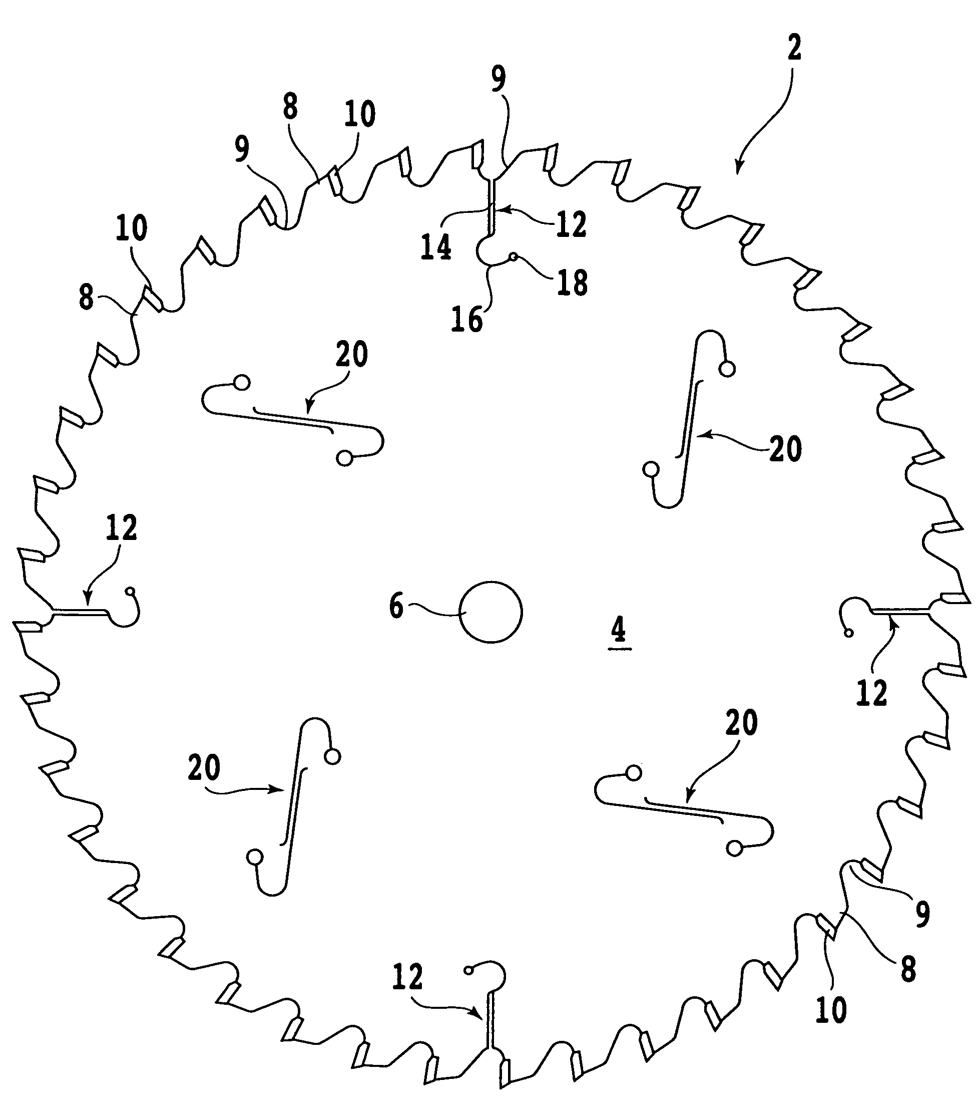
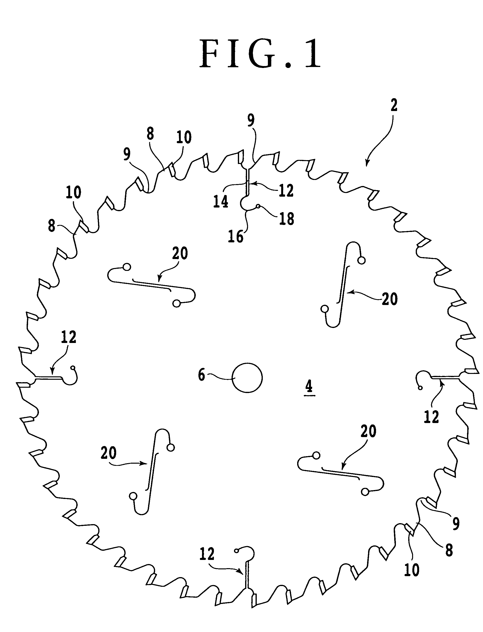
[0017]Referring to FIG. 1, there is shown a side view of a disk cutter 2 according to a preferred embodiment of the present invention. The disk cutter 2 is suitable for cutting of wood, steel, etc. The disk cutter 2 includes an annular disk-shaped base (base disk) 4 having a thickness of about 1.8 mm and a plurality of (e.g., 40) saw-toothed tip supports 8 formed along the outer circumference of the base disk 4 at equal intervals. A gullet 9 is defined between adjacent ones of the tip supports 8. The base disk 4 is formed of steel such as JIS SKS5 (alloy tool steel), JIS SK5 (carbon tool steel), or JIS SK6 (carbon tool steel). The diameter of the base disk 4 is about 255 mm, for example, and the base disk 4 has a central hole 6 having a diameter of about 16 mm, for example. However, these values are merely illustrative, and the disk cutter of the present invention is not limited to this preferred embodiment.

[0018]Each tip support 8 is formed with a recess (not shown), and a tip inse...


PUM

PropertyMeasurementUnit
frequencyaaaaaaaaaa
thicknessaaaaaaaaaa
diameteraaaaaaaaaa

Abstract

A disk cutter including an annular disk-shaped base, a plurality of tip supports formed integrally along an outer circumference of the base, a gullet is defined between adjacent ones of the tip supports, a plurality of tip inserts respectively fixed to the tip supports, a plurality of outer slits formed at an outer circumferential portion of the base at given intervals, each of the outer slits having an outer end opening to the gullet, a plurality of intermediate slit pairs formed at a radially intermediate portion of the base at the given intervals, each of the intermediate slit pairs is located between adjacent ones of the outer slits. Each intermediate slit pair includes a substantially J-shaped first slit and a substantially inverted J-shaped second slit arranged in point symmetrical relationship with the first slit. Each of the first and second slits is filled with a viscous material.

Description

BACKGROUND OF THE INVENTION[0001]1. Field of the Invention[0002]The present invention relates to a disk cutter or circular saw suitable for cutting of wood, steel, etc.[0003]2. Description of the Related Art[0004]A disk cutter or tip saw including a base disk having a plurality of tip supports arranged along the outer circumference and a plurality of hardened cutting tip inserts (cutter inserts) respectively fixed to the tip supports by brazing or the like is frequently used for board cutting or the like. The tip supports are spaced at given intervals in the circumferential direction of the base disk or annular disk-shaped base, and a gullet is defined between adjacent ones of the tip supports. Each tip support has a recess, and each hardened cutting tip insert is fixed in the recess of the corresponding tip support by brazing or the like.[0005]The base disk has a first mounting hole at its central portion, and a boss portion of a collar is inserted through the first mounting hole. ...

Claims


Application Information

Patent Timeline
Patent Type & Authority Patents(United States)
IPC IPC(8): B23D61/02B27B33/08
CPCB23D61/025Y10T83/9319Y10T83/9403
Inventor ASADA, TANEHIKO
Owner TENRYU SAW MFG
Why Eureka
Try Eureka